Single pole breakers open one conductor path; double pole breakers open two through a linked mechanism. A pole is a current-carrying path inside the breaker that has its own opening contacts. This difference determines which conductors are disconnected when the breaker operates. It does not, by itself, tell you the circuit voltage or current rating. To understand 1P and 2P, start with the wires passing through them.
How Single-Pole and Double-Pole Breakers Work
A circuit needs a complete path for current to flow. A single-pole breaker interrupts one part of that path, which is enough to stop normal load current. A double-pole breaker has two contact sets operated together, so it can interrupt two conductors serving the same load. Two poles therefore do not necessarily mean two separate circuits.
The opening mechanism also responds to faults. In a thermal-magnetic breaker, thermal protection responds to overloads, while magnetic protection responds rapidly to short-circuit current. The trip curve describes how current and operating time relate; the number printed on the handle is not an exact instantaneous trip threshold. These are distinct functions within the thermal-magnetic protection system.
Single-Pole vs Double-Pole Wiring
In the 1P line-and-neutral example below, the line conductor, marked L, passes through the breaker before reaching the load. The neutral conductor, marked N, connects to the load without passing through that breaker. There are still two conductors in the load circuit, but only one is switched by the 1P device.
In the 2P line-and-neutral example, L passes through one pole and N through the other. Both continue to the same load. The second pole adds a contact set in the neutral path, allowing both paths to open together. This illustrates one possible use of two poles; it does not mean that every double-pole breaker is wired to a neutral.
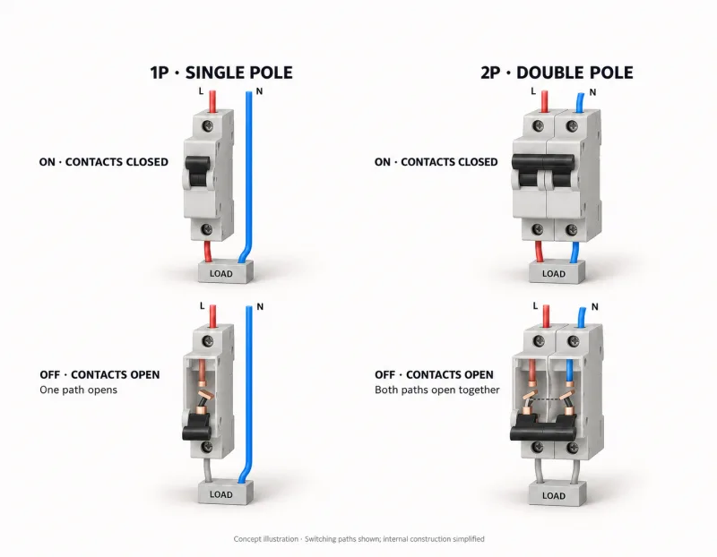
Read the top row as the connected state: closed contacts complete the load circuit. In the lower-left view, switching the 1P breaker OFF opens L while N remains connected. In the lower-right view, switching the 2P breaker OFF opens both L and N. Both arrangements interrupt normal load current, but they leave different connections between the supply and the load. The incoming side of either breaker can still be live.
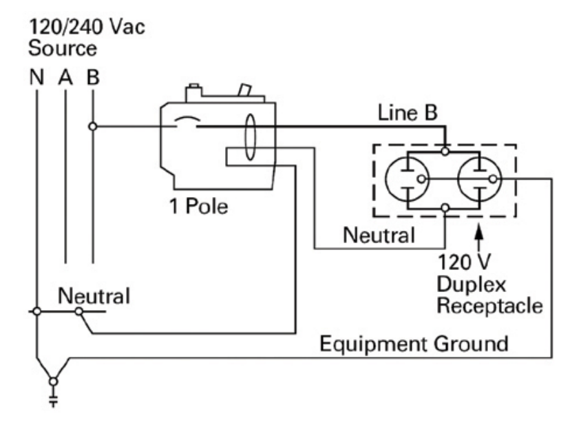
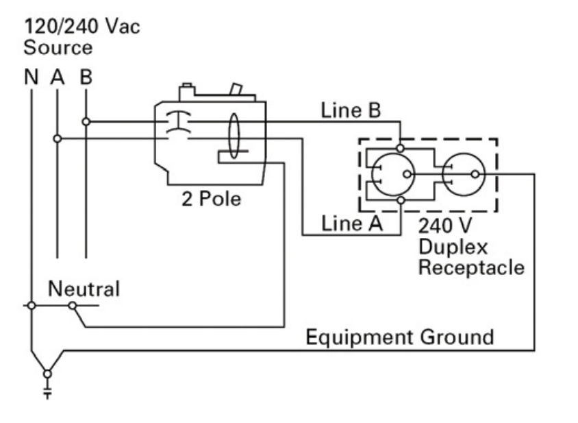
North American 120/240V wiring uses a different two-pole example. A 120V load uses one hot conductor and neutral. A 240V load connected between L1 and L2 uses two hot conductors, each passing through a pole of the double-pole breaker. Here, the second pole carries another hot conductor, not N. Follow the specific device diagram for terminal and neutral connections.
1P: 120V load
2P: 240V load
Opening both handles together is also different from opening both poles automatically during a fault. A common-trip breaker links its poles internally: a trip initiated by either protected pole opens the whole device. An external handle tie between two independent single-pole breakers does not create that internal mechanism. Schneider Electric's common-trip explanation makes this distinction explicit. The visible handle connection alone is therefore insufficient evidence of automatic common-trip operation.
Single Pole vs Double Pole: Key Differences
The comparison below describes conventional 1P and 2P overcurrent circuit breakers. It separates the paths that open from the poles that detect overcurrent, because those are different characteristics.
| Feature | Single pole: 1P | Double pole: 2P |
|---|---|---|
| Switched paths | One conductor path opens. | Two conductor paths open together. |
| Overcurrent-protected poles | One. | Two in a conventional fully protected 2P breaker. |
| Linked operation | One pole operates. | Both poles operate together; a common-trip device opens both automatically when either pole initiates a trip. |
| Installation space | Often one module or panel space in a standard product family. | Often two in the corresponding family; verify the actual dimensions and panel compatibility. |
1P+N needs a separate distinction. It switches line and neutral, but its neutral pole does not have its own overcurrent release. A conventional 2P breaker protects both poles. This is the distinction in Schneider Electric's 1P+N and 2P guidance. The two devices can therefore look similar in a simple opening-contact diagram. Our illustration shows switching paths, so it cannot establish the internal protection configuration; check the manufacturer's stated number of protected poles.
In Eaton's CH AFCI example, single-pole and two-pole versions occupy one and two panel spaces respectively. Other product designs can differ.
Current ratings do not add across poles. A 20A double-pole breaker is not a 40A breaker. Each pole has the specified 20A rating; the second pole adds another protected path, rather than extra current capacity to the first. Schneider Electric confirms this in its explanation of breaker ratings per pole. Voltage, current rating and pole count should therefore be read as separate specifications.
When to Use Each Type
For a typical 120V line-to-neutral branch circuit in a North American 120/240V system, single-pole protection is the usual arrangement. A 240V load supplied between the two hot conductors calls for a suitable double-pole breaker so those conductors are protected and disconnected together. The supply connection explains the choice more precisely than a broad rule about small and large appliances.
In a 230V line-to-neutral system, the voltage alone does not settle whether the neutral must also be switched. The installation's neutral-disconnection requirements and protection design determine whether 1P, 1P+N or 2P is appropriate. For example, the Clipsal A9D32616 RCBO is rated for 230–240V and explicitly lists 1P+N with one protected pole. It also provides residual-current protection, a function that pole count alone does not describe.
Once the required pole arrangement is clear, match the remaining specifications to the circuit. The voltage and AC/DC rating must suit the supply. The current rating and trip characteristic must suit the protected conductors and load, including starting current where relevant. The breaking capacity must suit the available fault current, and the breaker must be compatible with the distribution equipment. These are separate selection checks identified in Schneider Electric's Electrical Installation Guide; choosing 2P does not resolve them automatically.
The useful starting question is which conductors need protection and which need to open together. Answer that from the supply arrangement and load requirements, then select the breaker ratings and functions that fit. This keeps the choice between single pole and double pole tied to what the circuit actually needs.
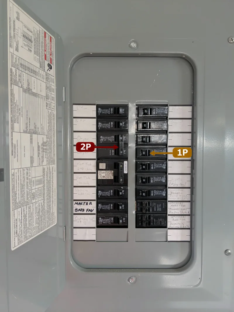
Cover photograph: Electrical panel opened by FuriousYogi, CC BY-SA 4.0 (with 1P and 2P annotations added).