

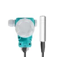


The 803 family uses a submerged pressure probe connected to a separate electronics head for continuous liquid level measurement. Choose the stainless steel 803/803S configuration for compatible noncorrosive liquids, or the PTFE 803F configuration for compatible acidic, alkaline and other corrosive liquids. Automatic temperature compensation and linear calibration support stable signal conversion.
| Model | Sensing construction | Display arrangement |
|---|---|---|
| 803 | Diffused-silicon sensor, 304 stainless steel probe housing and 316L diaphragm | Standard transmitter |
| 803S | Integrated local digital display | |
| 803F | Ceramic piezoresistive sensing core with PTFE probe and cable | Standard or digital-display version |
The stainless steel models serve water tanks, reservoirs, wells, municipal water and wastewater systems, fire-water storage, irrigation and compatible industrial liquids. The probe uses a three-layer protective structure, an optimized pressure inlet and a double-shielded vented cable.
| Parameter | 803 / 803S |
|---|---|
| Measurement principle | Hydrostatic gauge pressure |
| Sensor | Diffused silicon |
| Housing / diaphragm | 304 stainless steel / 316L stainless steel |
| Range choices | From 0-1m to 0-200m; customized ranges available |
| Accuracy | ±0.5%FS |
| Outputs | 4-20mA; optional RS485. A three-wire voltage configuration is also shown in the output wiring drawing. |
| Supply | 12-36VDC |
| Operating temperature | -20°C to 80°C |
| Protection | IP68 probe construction; three-layer protection |
| Overload capacity | 150%FS |
| Long-term stability | ≤0.2%FS/year |
| Cable and shielding | Vented cable with double copper-braided shielding |
| Electrical connection | Terminals inside the electronics head; cable connection to the probe |
| Installation | Submersible probe; M6 threaded fixing |
| Calibration | Automatic compensation and linear calibration |
| Display | 803S displays the liquid level locally |
| Customization | Measuring range, cable length and application specifications |


803F uses a ceramic sensing core, PTFE probe and PTFE cable with a 2088-style armored electronics enclosure. The combination is intended for compatible corrosive media in chemical processing, industrial storage, wastewater treatment, acid and alkali monitoring, and environmental process systems. Standard and digital-display versions are available. Calibration uses a Druck calibration system.
| Parameter | 803F |
|---|---|
| Product type | Corrosion-resistant submersible hydrostatic level transmitter |
| Measuring medium | Acidic liquids and corrosive media compatible with the wetted materials |
| Measuring range | 0-100m; customizable |
| Accuracy | ±0.5% standard; ±0.1% or ±0.25% optional |
| Supply | 24VDC standard; 15-30VDC |
| Outputs | 4-20mA standard; 0-5V, 0-10V or RS485 optional |
| Communications protocol | RS485 Modbus RTU, optional |
| Working temperature | 0°C to 70°C |
| Medium temperature | -20°C to 70°C; customized high-temperature versions up to 200°C |
| Temperature compensation range | -10°C to 70°C |
| Storage temperature | -10°C to 80°C |
| Temperature drift | ±0.01%FS/°C |
| Response time | 200ms |
| Installation | Submersible; M6 threaded mounting provision |
| Connection material | 304 stainless steel; PTFE optional |
| Probe and cable | PTFE |
| Overload capacity | 150%FS |
| Humidity | 0-95%RH |
| Protection | IP68 submersible probe construction |

The electronics head provides access to the output terminals and internal circuit board. Use the connection arrangement for the ordered output. The attached wiring sheet identifies two-wire loop-powered current, two-wire current with an external supply, three-wire voltage, and combined current/RS485 arrangements for the listed model families.


| Drawing dimension | 803 / 803S | 803F |
|---|---|---|
| Head width | 105mm | 106mm |
| Head height | 110mm | 108.5mm |
| Head lower connection length | 24.7mm | 27mm |
| Probe upper connection length | 33.5mm | 20mm |
| Probe body length | 101mm | 135mm |
| Probe body width / diameter callout | 28.5mm | 30mm |
| Lower-end callout | 13.3mm | 23.5mm |
| Thread callouts | M4 and M6 | |
The 803F installation sheet shows free-hanging, mounting-bracket, threaded and flange arrangements. The bracket illustration identifies a D60 mounting pipe. Each arrangement places the vented probe cable between the head and the submerged sensor and shows an approximately 5mm bottom dead zone. Use the attached drawings to identify the dimension endpoints and installation arrangement.
Bracket-mounted corrosion-resistant configurations are available with a 30mm probe for liquids compatible with PTFE and PVDF. ELE-803SF adds a four-digit LCD. Select the specific construction and signal version; these configurations have the ratings below.
| Parameter | ELE-803F bracket version | ELE-803SF bracket version |
|---|---|---|
| Range selections | 2–100mH₂O | |
| Pressure reference | Gauge | |
| Compatible media | Liquids compatible with PTFE and PVDF | |
| Probe diameter | 30mm | |
| Mounting | Bracket | |
| Output choices | Two-wire 4–20mA; three-wire 1–5V or 2–10VDC; four-wire RS485 | |
| Electrical entry | M20×1.5 | |
| 4–20mA supply | 10–30VDC | |
| 2–10V supply | 12–30VDC | |
| Accuracy | ±0.5% | |
| Overload | 1.5× full scale standard; special versions available | |
| Temperature | 0–60°C | |
| Probe protection | IP68 | |
| LCD | None | 4 digits |
