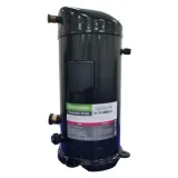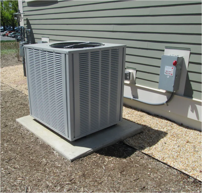
An HVAC compressor is the component in an air conditioner, heat pump or vapor-compression chiller that draws in refrigerant vapor and raises its pressure so the system can move heat. It helps maintain the low-pressure side where refrigerant absorbs heat and supplies the high-pressure side where heat is released. In a typical split air conditioner, it sits inside the outdoor unit; it is not the entire outdoor cabinet. Understanding that distinction matters when cooling fails: a problem with the fan, controls or starting components can leave a healthy compressor unable to operate.
How an HVAC Compressor Works
Refrigerant transfers heat by circulating through a closed circuit and changing between liquid and vapor. In cooling mode, the evaporator operates at a temperature low enough to absorb heat from indoor air. The compressor removes vapor from this low-pressure side and supplies it to the condenser at a higher pressure. That allows the refrigerant to reject heat at a temperature above the outdoor air. The compressor therefore provides both circulation and the pressure difference needed for the two heat exchangers to do different jobs.
The sequence is compressor → condenser → expansion device → evaporator → compressor. The compressor discharges hot vapor. In the condenser, that vapor loses heat and condenses into liquid. The expansion device restricts flow and drops the pressure; some liquid flashes into vapor. The resulting cold liquid-and-vapor mixture enters the evaporator, where the remaining liquid evaporates as it absorbs heat. Refrigerant returns to the compressor as vapor, normally with some superheat: a temperature above its saturation temperature at the suction pressure.
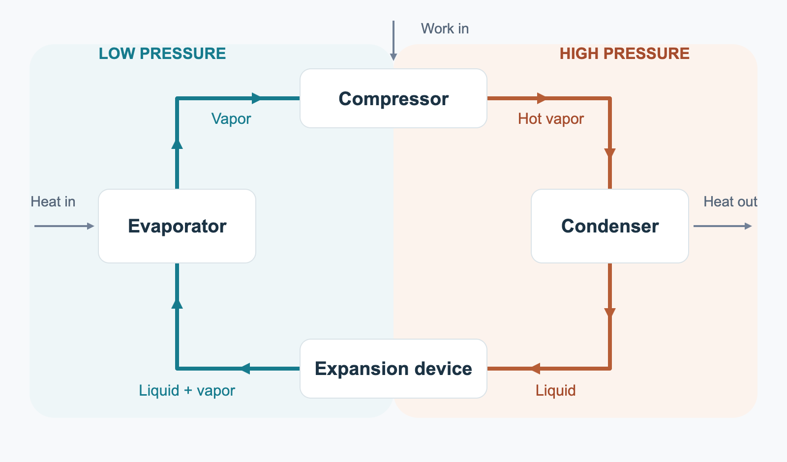
Compression also requires energy. The condenser must release the heat collected in the evaporator plus the energy added to the refrigerant during compression. This explains why the outdoor unit blows warm air while the room cools. Danfoss’s refrigeration fundamentals connects these component roles to refrigerant pressure, temperature and enthalpy—the energy carried by the fluid.
In a heat pump’s heating mode, a reversing valve changes the refrigerant route so the indoor coil releases heat and the outdoor coil absorbs it. The compressor still takes vapor through its suction connection and delivers it through its discharge connection. Reversing heating and cooling does not mean reversing the compressor’s rotation.
Types of HVAC Compressors
Compressor names describe several independent features. Scroll identifies a compression mechanism; variable-speed describes how output is controlled; hermetic describes the enclosure. One machine can be a variable-speed hermetic scroll compressor. Separating those categories makes comparisons more useful.
| Type | Compression method | Common applications | Main characteristics |
|---|---|---|---|
| Reciprocating | A piston draws vapor into a cylinder, then compresses and discharges it through valves. | Refrigeration systems and some air-conditioning equipment. | Broad range of sizes and constructions; piston motion and valve operation produce pulsating flow. |
| Scroll | An orbiting spiral and a fixed spiral trap vapor in shrinking pockets. | Central air conditioners, heat pumps, rooftop units and many chillers. | Compact mechanism with relatively smooth delivery; available with several capacity-control methods. |
| Rotary piston or vane | A rotating element reduces the volume of vapor trapped inside a chamber. | Room air conditioners, ductless systems and compact heat pumps. | Compact construction suited to smaller equipment; fixed- and variable-speed versions are available. |
| Screw | Helical rotors trap vapor and reduce its volume as it travels along the rotors. | Commercial chillers and larger refrigeration systems. | Continuous compression suited to larger duties; capacity control is important at reduced loads. |
| Centrifugal | An impeller accelerates vapor, and a diffuser converts part of its velocity into pressure. | Large building and process-cooling chillers. | Dynamic compression rather than shrinking trapped pockets; load and pressure lift affect stable operation. |
The first four mechanisms are positive-displacement designs: they compress a confined volume of vapor. Centrifugal compressors use fluid velocity to develop pressure. The structural drawings in Schneider Electric’s compressor white paper illustrate the distinction. In everyday HVAC descriptions, “rotary” often means a piston or vane design, although broader engineering classifications also place scroll and screw mechanisms in the rotary family. Application ranges overlap, so the type alone does not establish capacity, efficiency or service life.

Capacity control determines how output responds to demand. Fixed-speed equipment commonly cycles on and off or uses unloading to reduce capacity. A variable-speed design adjusts motor speed within its operating range. These approaches affect part-load operation, but variable speed is not a separate compression mechanism. Likewise, changing capacity does not always mean changing speed: some scroll designs vary output by unloading the compression mechanism.
Construction determines how the compressor is enclosed and accessed. A welded hermetic design seals the motor and mechanism inside a shell. A semi-hermetic design uses a housing that can be opened for specified service work. An open-drive compressor has a separate external drive, as in the photograph. These differences become especially important when deciding whether an internal fault can be repaired.
HVAC Compressor Repair or Replacement
An HVAC compressor repair decision begins with identifying what has actually failed. Poor airflow, inadequate condenser cooling, refrigerant problems or incorrect controls can interfere with operation without proving internal damage. For example, a dirty condenser or failed condenser fan can cause a high-pressure shutdown. The protection may be doing its job; replacing the compressor would leave the heat-rejection problem unresolved.
The first distinction is between a compressor that is not being allowed or helped to run and one that cannot perform its job despite correct operating conditions. The following symptoms help organize that investigation, but none identifies the failed part on its own.
| Observed symptom | What needs to be established |
|---|---|
| Fan runs, but cooling is absent | Whether the compressor receives a run command, actually operates and develops the expected pressure difference. |
| Humming, clicking or an unsuccessful start | Whether supply voltage and the specified starting components are correct before concluding that the mechanism is locked. |
| Starts, then repeatedly stops | Which thermostat, pressure control, drive or protector ends operation, and what condition triggers it. |
| Compressor runs, but output is weak | Whether airflow, refrigerant conditions and commanded capacity explain the complaint before diagnosing loss of pumping ability. |
Owners can record fault codes and operating symptoms, and check accessible filters and airflow obstructions. Electrical measurements and refrigerant-circuit work require a qualified technician; capacitors and drive electronics may retain hazardous charge after shutdown. Repeatedly resetting a tripping unit can turn an unresolved fault into further damage.
External Components and Controls
A failed capacitor, starting relay, contactor, connection or control device can stop the compressor without damaging its internal mechanism. The repair may therefore be a corrected connection or a replacement external component. If the compressor then operates correctly under normal system conditions, replacing the compressor assembly adds no remedy for the original fault.
The electrical design determines which components are present. Some fixed-speed single-phase compressors use a run capacitor and may also have a separate start capacitor and relay. Inverter-driven equipment relies on a drive and its own diagnostic procedure. A generic capacitor replacement or hard-start kit is not a universal solution. Nor does a click prove a bad relay: it may be a protector responding to a motor that cannot accelerate for another reason.
Copeland’s Starts/Runs troubleshooting guide separates voltage, wiring, starting-component and system faults from outcomes that justify compressor replacement. The useful result of that process is a specific diagnosis—such as a failed contactor or defective starting capacitor—followed by verification that the compressor and system now operate correctly.
Compressor Repair or Replacement
Internal failure requires stronger evidence than warm air or an unusual sound. Depending on the complaint, a technician may establish an electrical winding or insulation defect, an internal mechanical problem, or loss of pumping capacity after excluding external causes. An apparently open motor circuit must be distinguished from a thermal protector that has opened temporarily. Pressures and current also need operating context: refrigerant, load, mode and compressor speed or stage. There is no single pressure or current reading that proves every compressor healthy or faulty.
Once internal damage is confirmed, construction helps determine the remedy. A welded hermetic compressor is normally replaced as an assembly when its internal motor or mechanism fails. A serviceable semi-hermetic or open-drive compressor may permit internal repair, subject to the manufacturer’s procedures and the damage found. BITZER Green Point’s repair process, for example, includes inspection, assessment of internal parts, reassembly and final testing. That is compressor-body repair, a different job from replacing an external relay.
The failed component and the cause of failure may also be different. In Copeland’s failure-analysis training, liquid refrigerant returning during operation can dilute oil, undermine lubrication and contribute to mechanical wear and eventual motor damage. A flooded start is a related but distinct problem: refrigerant migrates and condenses during an off period. Replacing the damaged compressor without correcting the underlying conditions can expose the replacement to the same failure process.
Replacement also involves more than the price of a compressor. Refrigerant handling, removal and installation, contamination cleanup where needed, leak testing, evacuation and commissioning contribute to the job. Repairing a serviceable body brings its own inspection, parts, labor and testing costs. The comparison below applies to alternatives for the same installation, with comparable labor scope and warranty assumptions.
| Option | Relative cost | What changes the comparison |
|---|---|---|
| Repair an external fault or replace an accessory | Usually the lowest cost for a simple connection, capacitor or contactor fault. | Complex control boards or drives can be substantial repairs; the compressor itself must still be serviceable. |
| Repair a serviceable compressor body | Variable; potentially below assembly replacement when damage is limited. | Extent of wear, available parts, workshop labor and testing may remove the saving. |
| Replace the compressor assembly | Usually a larger repair than replacing simple external parts. | Access, refrigerant work, cleanup and warranty coverage can dominate the installed cost. |
| Replace the complete equipment or system | Usually the highest initial outlay, with a broader scope of renewal. | Its value improves when other major components also need work or support for the existing system is poor. |
Keeping the existing equipment is easier to justify when the coils, controls and remaining components are sound, the fault is isolated and repair coverage is useful. A complete replacement deserves comparison when several major parts are deteriorating, failures recur or compatible parts are difficult to obtain. Compare complete installed quotes and the warranty on the finished work. Carrier’s cost guidance identifies equipment size, installation, location and warranty as variables; a parts warranty should not be assumed to cover labor or refrigerant.
A sound decision names both the failed part and the work needed to restore reliable operation. For an accessory fault, that may mean keeping the compressor and repairing its support circuit. For confirmed internal damage, it means choosing between a permitted body repair, a replacement compressor or broader equipment renewal—and correcting the cause that damaged it.
Cover photo: NIST.