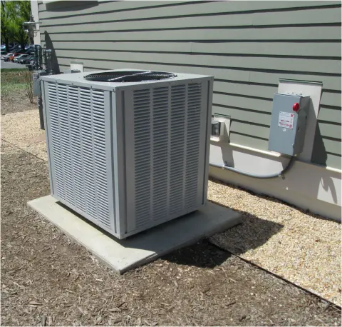
A motor start capacitor is a capacitor used briefly during startup in certain single-phase induction motors. Connected in series with an auxiliary winding, it changes the timing of the current in that winding so the motor can develop starting torque—the turning force needed to set the shaft and its load in motion. A starting switch or relay removes it from the circuit after the motor accelerates. This arrangement is useful in equipment such as pumps, air compressors and some refrigeration compressors, where getting a stationary load moving can be demanding. Not every single-phase motor has a separate start capacitor: the motor’s circuit determines whether it uses one, a continuously connected run capacitor, or another starting method.
How a Motor Start Capacitor Works
At standstill, a single main winding produces a magnetic field that pulses and reverses along a fixed axis. It does not establish a preferred direction of rotation. A capacitor-start motor adds an auxiliary winding displaced around the stator—the stationary part of the motor—and arranges for its current to reach its peaks at a different time from the main-winding current. The combination of winding position and current timing creates the rotating-field effect needed to start the rotor.
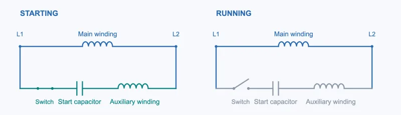
In the motor start circuit shown below, the supply is applied across two branches. One contains the main winding. The other contains a switch, the start capacitor and the auxiliary winding in series. During acceleration, the switch is closed and both branches carry current. In this capacitor-start, induction-run example, opening the switch interrupts the entire auxiliary branch while leaving the main winding supplied.
The capacitor repeatedly stores and releases energy as the AC voltage changes. Its useful effect here is a phase shift, meaning a difference in timing within each electrical cycle. An ideal capacitor’s current leads the voltage across that capacitor by 90 electrical degrees. However, the auxiliary branch also contains a winding with resistance and inductance, so the phase difference between the two motor-winding currents is determined by the whole circuit. It is not automatically 90 degrees in every motor or at every speed.
There is also no separate “input current” and “output current” to compare on opposite sides of the capacitor: in this series branch, the same current flows through the capacitor and the auxiliary winding. The useful comparison is between the main-winding current and the auxiliary-winding current. Their frequency remains the supply frequency; their timing and amplitudes differ. The illustration below uses equal normalized amplitudes and a 90-degree separation to make that timing difference visible, rather than to represent a measured motor.

As the motor accelerates, the starting device changes the circuit. A centrifugal switch responds to shaft speed. A current relay responds to motor current, while a potential relay responds to voltage associated with the auxiliary winding. These are different ways to determine when starting assistance should end. The capacitor itself neither measures speed nor opens the circuit.
How fast is the motor when the start capacitor disconnects? Roughly three-quarters of running speed is a useful description for many conventional capacitor-start designs, but it is not a universal setting. LEESON’s Basic Training gives approximately 75% of operating speed; Bodine’s motor handbook describes approximately 70% for its capacitor-start explanation. For a particular motor, the specified switch or relay characteristics govern the actual cutout point. A potential relay’s pickup voltage should not be treated as a fixed speed percentage shared by all compressors.
Removal matters because a start capacitor is designed for intermittent duty. Leaving it energized after its intended starting period can overheat and damage it. In the circuit above, the auxiliary winding is also intended to leave the circuit. In a motor with a separate run capacitor, the auxiliary winding can stay energized through that run capacitor after the start capacitor is switched out. The distinction is what allows the motor to use different electrical conditions for acceleration and normal operation.
Describing the start capacitor as a “boost” is therefore only shorthand. The supply provides the energy that accelerates the load; the capacitor helps establish a useful relationship between the winding currents. A larger capacitance is not automatically an improvement. Changing it changes the circuit, including the current in the auxiliary winding, and can produce an unsuitable operating condition.
Start Capacitor vs. Run Capacitor
A start capacitor is selected for the brief acceleration period. A run capacitor is designed to remain energized while the motor operates. Their different duties explain why apparently similar cylindrical components can be unsuitable substitutes for one another.
| Characteristic | Start capacitor | Run capacitor |
|---|---|---|
| Connection time | Briefly during acceleration, then removed by the starting device | Remains connected during normal operation; may also participate in starting |
| Typical construction | AC motor-start aluminum electrolytic construction | Low-loss film construction, commonly metallized polypropylene |
| Capacitance scale | Often tens to hundreds of microfarads | Often single-digit values to tens of microfarads, with larger values available |
| Published product-family example | 25–750 µF across one documented motor-start capacitor family | Cornell Dubilier Type SF: 1–100 µF across the series |
| Replacement requirement | Match the specified starting capacitance and intermittent-duty requirements | Match the specified running capacitance and continuous-duty requirements |
The two example ranges overlap. They describe product families, not a rule for identifying an unknown component or choosing a value for a motor. A 40 µF marking alone cannot tell you whether a capacitor is suitable for starting or continuous running. Read its duty and electrical ratings, then check the equipment diagram and parts specification.
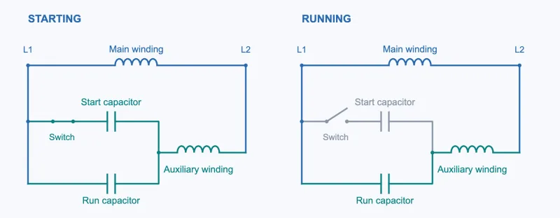
In a capacitor-start, induction-run motor, the starting branch is disconnected as shown in the circuit diagram in the previous section. In a capacitor-start, capacitor-run motor, the arrangement is different: during starting, the start capacitor is connected in parallel with the run capacitor, and their combined capacitance is in series with the auxiliary winding. In the diagram below, opening the start switch removes only the start-capacitor path. The run capacitor remains in series with the auxiliary winding, so both windings stay energized during normal operation.
A permanent split capacitor (PSC) motor uses a continuously connected run capacitor during both starting and running. Thus, a capacitor that helps a motor start is not necessarily an intermittent-duty “start capacitor.” Fitting a start capacitor in place of a PSC motor’s run capacitor would expose it to the wrong duty.
A dual run capacitor is a different arrangement again: two run-capacitor sections share one housing, commonly serving an HVAC compressor and fan. Two marked capacitances do not mean that one section is a start capacitor and the other is a run capacitor. A separate starting circuit may still be fitted to the compressor.
How to Read Capacitor Ratings
The label connects these circuit differences to the part in your hand. The photograph below shows a motor starting capacitor marked 540–648 µF, 330 VAC and −25 to +65°C. The capacitance range belongs to one capacitor; it is not two separate sections or an adjustable setting. On motor-component labels, MFD is also commonly used to mean microfarads.

Capacitance affects the current and phase relationship in the winding circuit. Use the motor or equipment manufacturer’s specified value or range. VAC identifies an AC voltage rating, not a voltage that the capacitor generates. The voltage across a motor capacitor can differ from the motor’s supply voltage, so selecting a replacement by the supply voltage alone is insufficient. A higher voltage rating does not give the motor more starting power.
Duty matters alongside those numbers. As a calculation example, a 1.67% duty ratio over a three-minute cycle corresponds to approximately three seconds energized per cycle, or twenty evenly spaced starts per hour. At the same duty ratio, a one-minute cycle corresponds to approximately one second energized per start, or sixty starts per hour. These calculations explain the duty ratio; the capacitor manufacturer’s specification determines which cycle lengths and starting durations are permitted. They do not establish the duty rating of the capacitor in the photograph or universal limits for other motors. Both the duration of each start and the interval between starts matter; repeated attempts to start a stalled motor can exceed the intended duty.
Some start capacitors have a discharge resistor across their terminals to reduce stored charge and electrical stress after switching. It does not replace the starting relay, and its presence does not establish that the capacitor is safe to touch. Preserve any resistor arrangement required by the equipment manufacturer.
For replacement, start with the specified part or an approved equivalent. Check capacitance, AC voltage rating, duty, temperature and frequency ratings, terminals, dimensions and mounting requirements. An approved higher-voltage replacement may be acceptable; a lower rating than specified is unsuitable. If the label is unreadable, use the motor or equipment model to find its parts documentation. A generic horsepower-to-capacitance estimate cannot account for the winding and starting-device design.
Motor Start Capacitor Failure Symptoms
A failed start capacitor can leave the motor without enough starting torque, but the sound or behavior of a struggling motor cannot identify the failed component by itself. An open auxiliary circuit, an unsuitable supply or a load that cannot turn can produce similar symptoms. The table separates useful observations from conclusions that still require checking.
| Observation | Possible connection to the capacitor | What else needs checking |
|---|---|---|
| Motor hums but does not turn | An open or degraded start capacitor can prevent adequate starting torque. | Starting switch or relay, auxiliary winding, supply voltage and a jammed or overloaded mechanism |
| Motor struggles to accelerate, then stops | The starting circuit may not provide the required torque; prolonged acceleration can stress the capacitor. | Load, voltage during starting and whether the motor’s overload protection has operated |
| MCB or fuse trips during starting | A shorted capacitor or an unsuccessful start may contribute to excessive current. | Wiring and winding faults, other circuit loads, starting-current duration and protection suitability |
| Capacitor is swollen, leaking or ruptured | There is visible damage requiring replacement. | Whether the specified part was fitted and whether the starting device removed it correctly |
| A replacement capacitor fails again | The replacement may be unsuitable or exposed to excessive starting duty. | Relay contacts, prolonged starting, low voltage, high starting load and excessive cycling |
A miniature circuit breaker (MCB) reacts to overcurrent according to its operating characteristics; it does not diagnose a capacitor. Normal motor starting current can exceed running current briefly without tripping correctly coordinated protection. Consequently, the timing of a trip and the measured current matter as well as the peak value. Repeated resetting or fitting a larger breaker is not a substitute for finding the cause.
A normal-looking capacitor may still be electrically defective. A competent technician can isolate the equipment, verify that power is absent, discharge the capacitor using the appropriate procedure and confirm discharge before measurement. The capacitor should be isolated from the circuit for a meaningful capacitance reading, using an instrument with a suitable range. Compare the reading with the specified range or tolerance; an over-range indication alone does not prove failure. Further checks of the starting device and motor may still be necessary.
If a new capacitor fails soon after replacement, investigate what kept the motor in its starting condition or kept the capacitor connected. Replacing the visible casualty without correcting that condition invites another failure. The essential distinction is the same throughout: a motor start capacitor establishes useful winding current during acceleration, and a correctly matched starting circuit removes it when that brief task is complete.