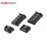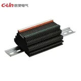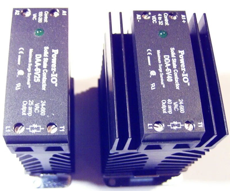
A high-speed relay is useful when the delay between a control command and a change in the circuit affects the result. That result might be a measurement becoming ready, a DC load turning on, or a trip coil receiving power. Each application places a different demand on the relay, so an operating-time figure becomes useful only when it is read alongside the circuit the device will switch.
When comparing high-speed relays and high frequency relays, put two specifications side by side: how quickly the contacts or semiconductor output respond, and the frequency of the signal or power passing through that output. A relay can carry a GHz signal while taking milliseconds to change its contact position. This guide uses manufacturer specifications to compare those two dimensions, then explains the choices for RF routing, solid-state switching and fast tripping.
Relay Comparison: Operating Time and Circuit Frequency
Operating time describes a response to a control input. Circuit frequency describes the electrical waveform at the switched terminals. A third specification, operating frequency, describes how often the relay may be commanded through switching cycles. The table uses representative figures from the manufacturer examples discussed below. Timing and frequency limits vary by model and operating conditions.
| Relay type | Contact or output operating time | Switched-circuit frequency |
|---|---|---|
| RF relay | 3ms maximum | RF signal up to 3GHz |
| DC-output solid-state relay | 1ms maximum turn-on time with DC control input | DC load circuit |
| AC zero-cross solid-state relay | 11ms maximum turn-on time at 50Hz with DC control input | 50Hz AC load circuit in this example |
| High-speed contactor relay | Less than 8ms | DC trip circuit |
The RF frequency describes the signal passing through the relay. The AC frequency belongs to the load supply. A DC circuit has no repeating supply cycle.
Use the table to identify a suitable technology, then compare complete part numbers under the same conditions. Maximum operating time is more useful for a timing budget than a typical value, and turn-off or release time needs its own check.
RF and High-Frequency Relays
RF means radio frequency. In an RF relay, the contacts establish a path for a high-frequency signal, such as a connection between a test instrument and a device being measured. Once the contacts have settled, the signal passes through that path while the contacts remain in position. The mechanical switching event and the signal's repeating waveform therefore run on different timescales.
The OMRON G6K-2F-RF-T handles signals up to 3GHz and has a maximum operating time of 3ms. The suffix matters because other G6K-RF versions have different frequency specifications. OMRON specifies RF characteristics using a defined test board and impedance, so the surrounding PCB layout forms part of the signal path. (OMRON G6K-RF datasheet)
A useful RF comparison goes beyond the upper frequency limit. Insertion loss describes signal lost along the selected path. Isolation describes how well an unwanted path is suppressed. Impedance matching affects reflected energy, while repeatability matters when a measurement is repeated after many switching cycles. These parameters are central to Keysight's RF switching selection guidance.
For a test fixture, choose a relay with suitable signal performance across the required band, then allow time for the switching path and measurement to settle before acquiring data. A short actuation delay alone cannot establish measurement accuracy.
Solid-State Relays
A solid-state relay, or SSR, uses a semiconductor output instead of moving contacts. This removes mechanical contact bounce and contact wear from the switching process. The output circuit still determines which loads it can control and how quickly it responds. In particular, distinguish the control input from the load output: an SSR controlled by a DC signal may switch either an AC load or a DC load, depending on its design.
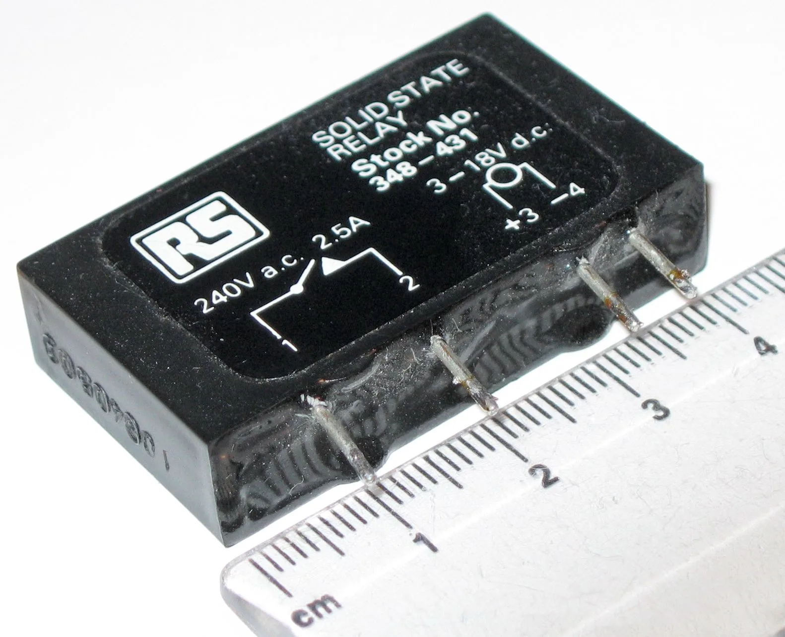
For DC switching, examine both edges of the response. With a DC control input, the OMRON G3NA-D210B-UTU has a maximum turn-on time of 1ms and a maximum turn-off time of 5ms. A process that requires a quick release must account for the longer value. An inductive load may also continue responding after the electronic output changes state, so relay timing and load response should be checked separately.
For AC switching, a zero-cross SSR waits until the load-supply voltage is near zero before turning on. This behavior ties its response to the AC waveform and can be useful for reducing switching disturbance in suitable loads. It explains why an AC SSR can have a longer command-to-output delay than a DC SSR despite having no moving parts.
With a DC control input, the OMRON G3NA-220B-UTU specifies a maximum turn-on delay of half a load-supply cycle plus 1ms. A 50Hz supply has a 20ms cycle, giving a maximum delay of 11ms (10ms + 1ms). (OMRON G3NA specifications)
Turn-off follows a different rule in AC SSRs that use triacs or thyristors. As OMRON explains, removing the gate drive does not immediately stop conduction: the device continues conducting until current reaches zero. Voltage zero and current zero need to be distinguished, particularly with inductive loads. A random-turn-on AC SSR can remove the voltage-zero waiting condition at turn-on, but that does not make a triac output suitable for interrupting DC.
Also distinguish output leakage from control-to-load isolation. An optically isolated SSR can provide isolation between its input and output while allowing a small leakage current through its switched output in the off state. OMRON's SSR terminology treats these as separate characteristics. Check whether that leakage affects the load, and provide the heat dissipation required for the output's on-state losses. Semiconductor temperature and surge limits still apply.
High-Speed Contactor Relays
High-speed contactor relays serve applications where a fast mechanical contact action must also energize a demanding load. A typical example is a protection system that uses an auxiliary relay to supply a circuit-breaker trip coil. Here, the important combination is operating delay, contact arrangement and the ability to handle the specified inductive circuit.
Arteche describes its high-speed contactor relay family as operating in less than 8ms, with variants providing two to eight changeover contacts. Its published making-capacity example is 40A for 0.5s at 110VDC. That short-duration closing rating must be read separately from continuous carrying current and the current the contacts can interrupt. The selected model's load ratings remain essential even when its timing is suitable. (Arteche high-speed contactor relay specifications)
In a trip system, relay operation is one stage of the response. Fault detection, command processing, trip-coil operation and breaker interruption also take time. Specify the required contact action and the complete trip sequence before deciding whether a particular relay meets the system's timing requirement.
How to Choose a High-Speed Relay
Start by describing the circuit at the relay output. Record whether it carries an RF signal, AC power or DC power; include voltage, normal current, inrush or pulse current, and the nature of the load. Then describe the control source and required contact or output arrangement. This prevents a fast device from reaching the shortlist when its electrical function is unsuitable.
Next, define the event that must happen by the deadline. It could be first contact closure, a stable measurement path, load current falling below a limit, or a breaker completing interruption. Build the timing budget around that event. Include controller delay, relay turn-on or turn-off, contact bounce or settling where relevant, and the load's own response. Check how the manufacturer defines each timing specification so that a settling allowance is neither omitted nor counted twice.
For example, if a DC output must turn off within 2ms of the controller command, the G3NA-D210B-UTU example's 5ms maximum turn-off time would already exceed the budget. Its 1ms turn-on figure would not resolve that requirement. This is a specification comparison, rather than a measurement of a complete installation.
Check repetition separately from single-operation speed. Taking the reciprocal of a millisecond operating-time value does not establish an allowed switching rate. A repeated cycle includes energizing, releasing and any required dwell time. Mechanical and electrical endurance also describe different conditions: a no-load cycle rating cannot establish life while switching a particular load. For an SSR, repeated switching still has to remain within the output device's thermal and electrical limits.
Finally, use the technology-specific checks that follow from the application. RF routing needs signal integrity across the intended band. DC solid-state switching needs suitable output polarity, off-state behavior and response in both directions. AC solid-state switching needs the right zero-cross behavior and load compatibility. Fast trip duty needs the required contact arrangement and verified making, carrying and breaking ratings.
The best high-speed relay is the one whose specified response fits the complete timing budget while its output suits the circuit. Writing down operating time and circuit frequency together makes that decision clearer—and gives you a practical starting point for comparing datasheets and validating the assembled system.