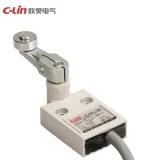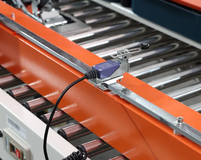
A micro switch is a compact snap-action component that can be built into a mechanism. An industrial mechanical limit switch is a position-sensing assembly with a machine-mountable housing, an external actuator and a way to connect field wiring. A micro switch suits a protected spot where the moving part can reach it directly. An enclosed limit switch suits a point where the switch needs its own mount, an actuator that matches the machine’s motion and protection for the wiring.
Micro Switch vs. Limit Switch at a Glance
| Feature | Micro switch | Industrial mechanical limit switch |
|---|---|---|
| Construction | Compact switch with a spring-driven snap-action mechanism. | Enclosed assembly with an operating head that transfers motion to the internal contacts. |
| Typical mounting | Built into a device or mounted inside a mechanism, close to the moving part. | Bolted to a machine frame or bracket to detect a position along the travel path. |
| How it is triggered | A tab or link presses a short plunger, a lever or a small roller. | A moving part or cam drives an external plunger, roller lever or other operating head. |
| Wiring and protection | Common versions have exposed terminals or molded leads. Sealed versions are available. | The housing protects the mechanism and provides a cable entry, connector or prewired cable. Protection varies by model. |
The two types overlap in how they switch. In a snap-action mechanism, reaching the operating point releases spring energy and moves the contact quickly. Many enclosed limit switches use this same action internally. A micro switch can also perform limit detection on its own when the moving part reliably trips it and the installation provides the protection it needs.
How the Moving Part Reaches the Switch
Picture a packaging machine with two position checks. Inside the housing, a small tab presses a micro switch to confirm that a carton guide is in place. At the conveyor transfer, a cam on a moving carriage sweeps past a roller-lever limit switch mounted to the frame. Both switches report position to the programmable logic controller (PLC).
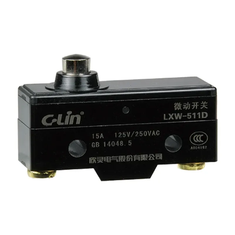
At the carton guide, the tab can push a pin plunger in line with its stroke. The guide and switch mount keep the two parts aligned, and the machine housing can help shield the switch and its terminals. Check the stroke at the extremes of assembly tolerance. The tab needs enough movement to reach the operating point on every cycle and enough clearance to let the plunger release when the guide moves away.
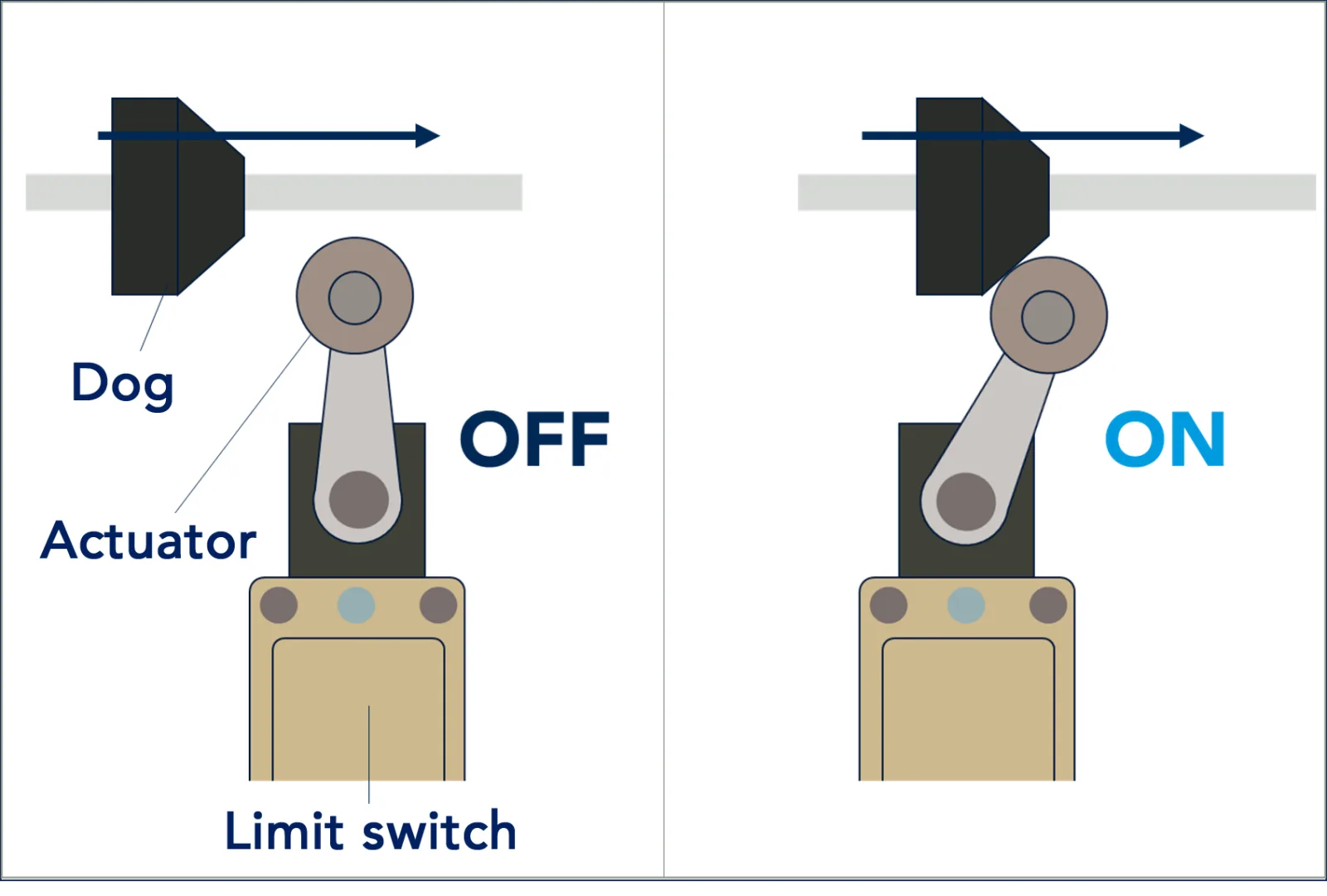
At the transfer carriage, the cam first touches the roller and then turns the lever far enough for the contacts to change state. If the carriage keeps moving, the lever can turn farther. That extra actuator movement after switching is called overtravel. The shape of the cam and the length of the lever determine how the carriage’s linear movement translates into lever rotation. Use the switch drawing to check both the approach direction and the resulting actuator travel through the full pass.
What to Check on the Datasheet
The actuator can change the force and travel requirements even within one micro switch family. The D2VW datasheet lists a maximum operating force of 1.96N and a maximum pretravel of 1.2mm for the D2VW-01-1M pin-plunger model. For the D2VW-01L1B-1M long-lever model, those limits are 0.59N and 9.0mm in the specified actuation direction. Pretravel is the actuator movement from rest to the point where the contacts change state. The long lever can be easier to push and still need more room to move. For the carton guide, both limits matter.
The protection ratings can overlap, too. A D2VW with molded leads and an Omron D4C enclosed limit switch can both meet IP67. The molded-lead D2VW seals the wire exit, while the D2VW terminal version excludes the terminals from its IP67 rating. The D4C encloses the mechanism and seals the cable entrance. Check where the wires will be joined and what they will be exposed to. If the conveyor is cleaned with a chemical solution, verify that the seals and cable jacket are suitable for that solution.
| Check | What it tells you |
|---|---|
| Actuator drawing, force and stroke | Whether the moving part can trip and release the switch reliably while keeping any overtravel within the manufacturer’s specified range. |
| Mounting, cable entry and sealing | Whether the switch fits the available space and the installed wiring is protected from the conditions at that point. |
| Contact arrangement and electrical load | Whether the contacts give the required input state and can switch the actual circuit, including a low-current PLC input. |
For the PLC input, check its voltage and current against the switch’s applicable load range. A maximum current rating tells you how much load the contacts can switch under specified conditions. The minimum applicable load helps you select contacts for a small signal. A low-current input may call for a version rated for microloads.
How to Verify the Switch After Installation
Suppose the roller switch on the transfer carriage needs replacing. Cross-check the full part number, mounting holes, roller position, lever length, actuation direction and contacts. Then cycle the carriage through its normal motion and watch the physical actuator and the PLC input. Verify where the input changes, how long it stays in that state and where it returns. A replacement can fit the same holes and still move the point where the signal changes.
If the signal comes on early at the same spot on every pass, start with the roller position, the cam’s point of contact and the bracket alignment. If the PLC counts more than once on a single pass, check for a lever that rebounds or a bracket that lets the actuator move. Mechanical contacts can also briefly make and break as they settle, a phenomenon called contact bounce. Watching the motion alongside the input trace helps you tell whether the lever is being actuated again or the contacts are momentarily bouncing during one actuation.
The protected carton guide suits a compact micro switch because the guide itself provides repeatable alignment. The frame-mounted roller switch suits the transfer carriage because it can take motion from the passing cam and protect its wiring entry. Either choice comes down to what the PLC sees after installation. The signal should change at the intended position and reset reliably through the full cycle.