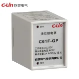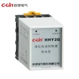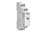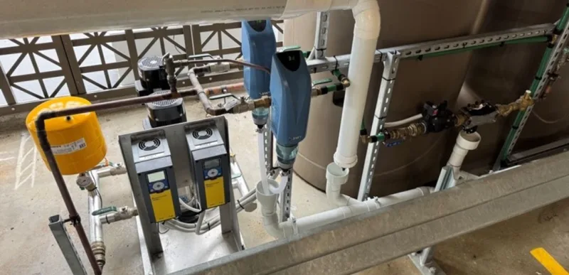
A water tank is halfway between its two level probes. One minute the pump is running. Later, at the same water level, the pump is off. Both states are normal in a two-point control system. A liquid level control relay uses one level to start the pump and another to stop it. Between those points, it holds the previous command.
For a tank that contains a conductive liquid, the first decisions are what the pump should do at each level, whether the liquid can be detected reliably, and what the relay output needs to switch. Those decisions determine the controller, probes, and motor control components you need.
How a Liquid Level Control Relay Detects Water
A conductive level relay applies a sensing signal between a common electrode and a measuring electrode. When water covers both tips, it provides a path for current. The controller compares the resistance of that path with its detection threshold. When the water drops clear of the measuring tip, the path opens or its resistance rises enough for the controller to register a dry probe. Each measuring tip marks a fixed point in the tank.
A typical three-electrode setup has a short probe for the upper switching point, a longer probe for the lower switching point, and a common electrode that extends below both. The common electrode provides a return path at either switching point. Because the controller knows which probes are wet and retains its current command between the two levels, a ripple near a single probe is less likely to make the pump start and stop repeatedly.
Filling vs. Draining: When Does the Pump Run?
In filling mode, the pump starts when the level falls below the low probe. It continues running as water rises past that probe and stops when the water reaches the high probe. In draining mode, the pump starts when the rising water reaches the high probe. It continues pumping as the water falls and stops when the level drops below the low probe.
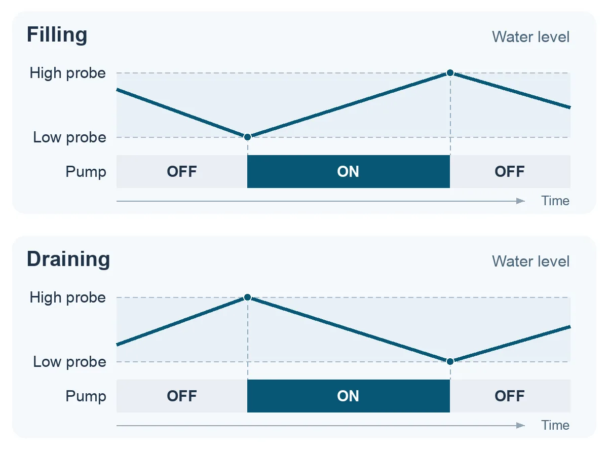
Place the two switching points around the usable volume you want to move each cycle. A small volume between the probes can mean frequent starts even when the controller is working correctly. Leave room above the high point for any inflow that continues after shutdown, and set the low point with the pump intake and required water coverage in mind. If power returns while the water is between the probes, verify the restart behavior in the manual for the specific controller.
How to Wire a Liquid Level Control Relay
This example uses a GEYA GRL8-02 in two-level mode. Connect the high probe to Max, the low probe to Min, and the common electrode to C. In the example below, a protected 24VAC control supply powers the relay at A1 and A2. The probe common C belongs to the sensing circuit. The output common 11 belongs to the changeover contact.
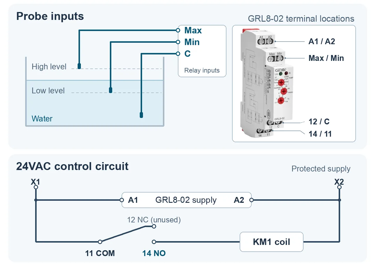
Terminal 11 receives one side of the control supply. The normally open contact at 14 feeds the matching 24VAC contactor coil, labeled KM1. The other side of the coil returns to the control supply. Terminal 12 is the normally closed contact and is unused in this example. When 11–14 closes, KM1’s main contacts switch power to the pump through the separate motor circuit.
Set the pump selector to position 2 on the UP side for filling or position 2 on the DOWN side for draining. Both modes use the same connections in this example. Use the GRL8-01 and GRL8-02 instruction manual (PDF) to check the terminal layout and selector positions against the relay before installation.
How to Choose the Relay and Probes
Start with the liquid. Conductive detection depends on the resistance between the installed electrodes. The reading depends on the liquid as well as the probe geometry and spacing. Very low-conductivity water may need a more sensitive controller. Oil generally calls for a different sensing method, such as a compatible float switch. For an uncertain water application, compare the wet and dry readings with the manufacturer’s operate and release specifications. Excessive sensitivity can make a damp electrode holder look like a wet probe.
OMRON’s K8AK-LS1, for example, has an adjustable operating-resistance setting from 10kΩ to 100kΩ. That range describes the controller’s threshold for the electrical path between the electrodes. Check what the probes actually see in the tank before choosing a setting.
Specify the installation. Confirm filling or draining mode and the available control supply voltage. Some relays let you select the mode on the device, while others use separate model variants. Check the permitted probe cable length for the exact model and cable type. Choose the electrode and holder to suit the liquid, temperature, and tank mounting. In a tank prone to scale or sludge, provide access to inspect and clean the electrodes so deposits do not interfere with detection.
Check what the output switches. In the wiring example, the contactor coil is the load on the level relay’s output. Verify the coil voltage and inrush against the relay’s inductive switching rating. Select the contactor and motor protection for the pump. For direct motor switching, use the manufacturer’s motor-load rating and check it against the pump’s starting and running currents.
Does the System Also Need Dry-Run Protection?
Consider a pump that transfers water from a ground-level reservoir to an elevated tank. The elevated tank drops below its low probe and calls for water, but the source reservoir is nearly empty. The pump can respond to the fill request only while the source level is above its dry-run cutoff. A separate low-level input at the source can inhibit startup and stop a running pump if the source runs low. OMRON’s 61F application guide shows this arrangement with separate electrodes for the receiving tank and the water source.
Before ordering, write down the pump’s start and stop levels and the conditions that should prevent it from running. The answers tell you whether a standard two-point relay is sufficient and which additional inputs you need.