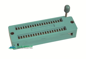
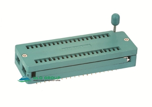
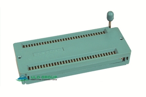
ZS431, ZS431A, ZS432 and ZS432A use lever-operated zero insertion force socket structures with through-hole PCB terminals. Select longitudinal pitch, contact count and PCB row spacing together. Each model has a distinct body and lever-clearance drawing.
| Model | Longitudinal pitch | Total contacts | PCB terminal-row spacing |
|---|---|---|---|
| ULO-ZS431 | 2.54mm | 24, 28, 32, 40, 48 | 15.24mm |
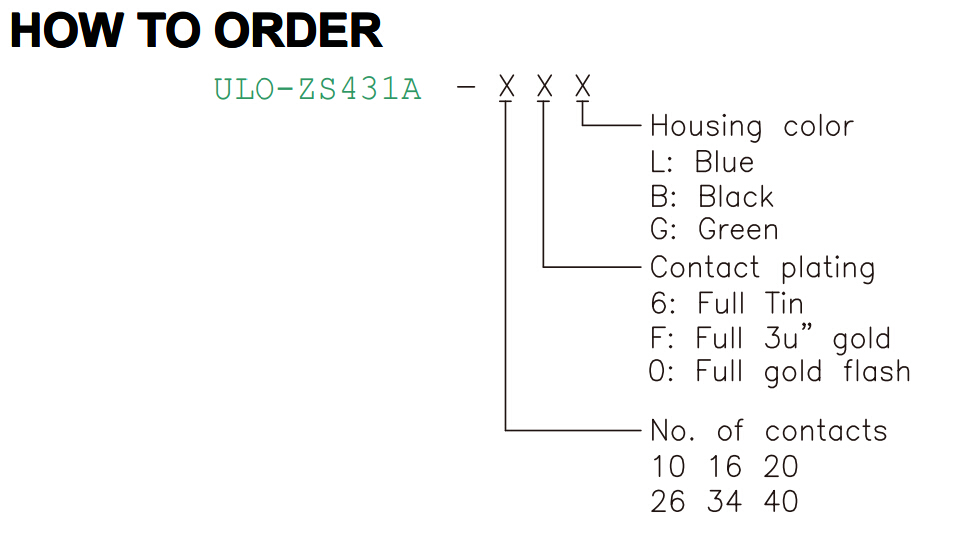
| ULO-ZS431A | 2.0mm | 10, 16, 20, 26, 34, 40 | 10.00mm in the illustrated 40-contact outline |
| ULO-ZS432 | 2.54mm | 14, 16, 20, 24, 28, 32, 40, 48 | 7.62mm for 14–28 contacts; 15.24mm for 32–48 contacts |
| ULO-ZS432A | 1.778mm | 28, 32, 42, 56, 64, 90 | 10.16mm, 15.24mm, 20.70mm or 22.86mm according to count |
Each socket has two contact rows. Longitudinal pitch and transverse terminal-row spacing are separate dimensions.
| Characteristic | All four models |
|---|---|
| Rated voltage and current | 50VDC, 100mA |
| Insulation resistance | ≥1000MΩ |
| Withstand test | 500VAC for 1 minute |
| Operating life | 5000 cycles with load |
| Operating temperature | -25°C to +70°C |
| Storage temperature | -40°C to +85°C |
| Humidity test condition | 95%RH at 40°C for 48 hours |
| Solderability test | After flux application, 230°C for 5 ±0.5 seconds; 95% coverage |
| Resistance to soldering heat | 260°C ±5°C for 5 ±1 seconds |
The 500VAC value is a one-minute withstand test, distinct from the 50VDC rating. The cycle-life statement specifies operation with load without separately detailing the life-test load. Solderability and heat-resistance entries are test conditions.
| Material characteristic | Specification |
|---|---|
| Housing | Thermoplastic |
| Insulating material group | I |
| Flammability classification | UL94V-0 |
| Contact material | Copper alloy |
| Field | ZS431 and ZS432 | ZS431A and ZS432A |
|---|---|---|
| Housing colour | L: blue; B: black; G: green | L: blue; B: black; G: green |
| Contact plating | 6: full tin; F: full 3µin gold | 6: full tin; F: full 3µin gold; 0: full gold flash |
The order sequence combines the model, contact count, plating code and housing colour. Gold flash code 0 belongs to the A-suffix models.

A is overall body length and B is the centre distance between the end fastener references. Values are in millimetres.
| Contacts | A | B |
|---|---|---|
| 24 | 45.3 | 40.9 |
| 28 | 50.4 | 46.0 |
| 32 | 55.5 | 51.1 |
| 40 | 65.6 | 61.2 |
| 48 | 75.8 | 71.4 |
Body width is 22.90mm, with 18.50mm and 7.10mm top-view references. PCB row spacing is 15.24mm. Housing height is 11.20mm; raised-lever clearance is 22.9mm reference. PCB leads project 3.2mm, with 0.80mm and 0.35mm terminal dimensions and a 0.50mm lower reference. For N contacts per row, the end-pin span is (N − 1) × 2.54mm; the lever-side end offset is 10.5mm.

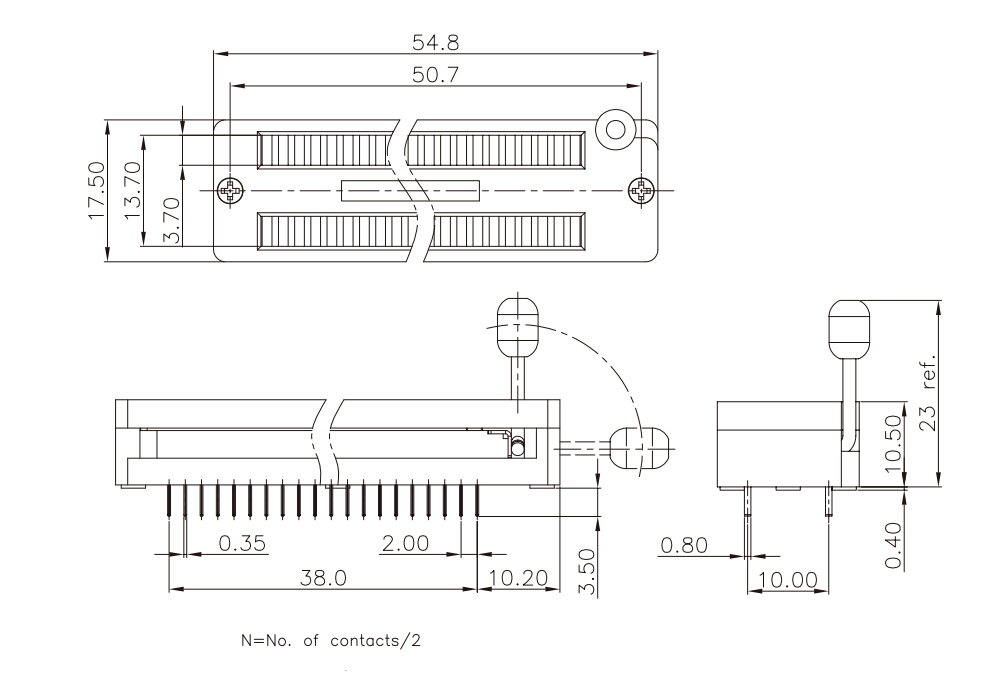
The dimensioned outline has a 38.0mm end-pin span at 2.00mm pitch, corresponding to 20 positions per row and 40 contacts total. Its dimensions should not be extended to other counts without their matching outline.
| Illustrated 40-contact feature | Dimension |
|---|---|
| Overall body length | 54.8mm |
| End fastener reference spacing | 50.7mm |
| Body width | 17.50mm |
| Top-view inner references | 13.70mm and 3.70mm |
| PCB terminal-row spacing | 10.00mm |
| Housing height | 10.50mm |
| Raised-lever clearance | 23mm reference |
| PCB lead projection | 3.50mm |
| Terminal dimensions | 0.80mm and 0.35mm |
| Lower reference | 0.40mm |
| Lever-side end offset | 10.20mm |

A is overall body length, B is end fastener reference spacing, C is the inner transverse reference, D is overall body width and E is PCB terminal-row spacing. Values are in millimetres.
| Contacts | A | B | C | D | E |
|---|---|---|---|---|---|
| 14 | 32.6 | 28.2 | 11.22 | 14.90 | 7.62 |
| 16 | 35.1 | 30.7 | |||
| 20 | 40.2 | 35.8 | |||
| 24 | 45.3 | 40.9 | |||
| 28 | 50.4 | 46.0 | |||
| 32 | 55.5 | 51.1 | 18.84 | 22.52 | 15.24 |
| 40 | 65.6 | 61.2 | |||
| 48 | 75.8 | 71.4 |
Housing height is 11.20mm and raised-lever clearance is 22.9mm reference. PCB leads project 3.2mm, with 0.80mm and 0.35mm terminal dimensions. The top-view slot reference is 3.60mm. For N contacts per row, end-pin span is (N − 1) × 2.54mm; lever-side end offset is 10.5mm.


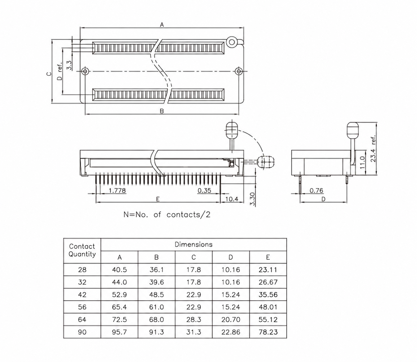
A is overall body length, B is end fastener reference spacing, C is body width, D is PCB terminal-row spacing and E is end-pin span along a row. E is the nominal span calculated as (contacts/2 − 1) × 1.778mm, rounded to two decimal places. Values are in millimetres.
| Contacts | A | B | C | D | E nominal |
|---|---|---|---|---|---|
| 28 | 40.5 | 36.1 | 17.8 | 10.16 | 23.11 |
| 32 | 44.0 | 39.6 | 17.8 | 10.16 | 26.67 |
| 42 | 52.9 | 48.5 | 22.9 | 15.24 | 35.56 |
| 56 | 65.4 | 61.0 | 22.9 | 15.24 | 48.01 |
| 64 | 72.5 | 68.0 | 28.3 | 20.70 | 55.12 |
| 90 | 95.7 | 91.3 | 31.3 | 22.86 | 78.23 |
Housing height is 11.0mm, raised-lever clearance is 23.4mm reference, and lead projection is 3.30mm. Terminal dimensions are 0.76mm and 0.35mm. The upper slot reference is 3.3mm and lever-side end offset is 10.4mm.