
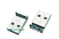
| Part Number: | ULO | - | USB485 | - | B | N | 03 |
|---|---|---|---|---|---|---|---|
| Explanation: |
Brand |
Model USB485 - Type A plug with through-hole signal tails |
Housing Colour W - White |
Shell Plating N - Nickel |
Contact Plating 0 - Selective gold flash |
USB485 and USB486 are four-contact USB Type A male plugs. USB485 uses through-hole signal tails; USB486 uses SMT signal tails. Both have separate shell mounting slots and locating holes in their recommended PCB patterns. Select the signal termination style before laying out the board.
| Characteristic | USB485 | USB486 |
|---|---|---|
| Interface | Type A male; 4 contacts | Type A male; 4 contacts |
| Signal termination | Through-hole | SMT |
| Overall length reference | 19.85mm | 20.85mm |
| Shell length reference | 18.65mm | 18.65mm |
| Plan width | 11.92mm | 12mm |
| Shell height | 4.50mm | 4.50mm |
| Contact section | 0.20×0.60mm | 0.20×0.60mm |
| Characteristic | Value for both models |
|---|---|
| Rated current | 1.5A |
| Rated voltage | 30V; AC/DC designation unspecified |
| Contact resistance | ≤50mΩ |
| Insulation resistance | 100MΩ; minimum/maximum designation unspecified |
| Dielectric withstand test | 100VAC for 1 minute |
| Insulator | PA66; material group I; UL94V-0 |
| Contacts | Copper alloy |
USB generation, data rate and charging protocol are unspecified. The 100VAC value is a dielectric test condition, separate from the rated voltage.
The three fields after the model number specify housing colour, shell plating and contact plating. The model number determines the signal termination style.
| Field | Code | Selection |
|---|---|---|
| Housing colour | W / B | White / black |
| Shell plating | N / 6 | Nickel / tin |
| Contact plating | 0 / 03 / 30 | Selective gold flash / selective gold 3µin / selective gold 30µin |
| Reference | Dimension |
|---|---|
| Signal holes | Four Ø0.92mm holes |
| Signal-hole centre spacing | 7mm outer span; 2mm between the middle pair |
| Locating holes | Two Ø1.40mm holes at 4.50mm centres |
| Shell mounting slots | Two 1×2.50mm slots at 11.70mm centres |
| Slot pad envelope | 1.40×3.80mm |
| Locating-hole row to PCB edge | 2.60mm REF |
| Other body references | 14.65mm and 2mm along the side view; 5.80mm rear spread; 2.90mm and 1.35mm terminal references |
| PCB layout tolerance | ±0.05mm |

| Reference | Dimension |
|---|---|
| Signal pads | Four 1×2.70mm pads |
| Signal-pad centre spacing | 7mm outer span; 2mm between the middle pair |
| Locating holes | Two Ø1.40mm holes at 4.50mm centres |
| Shell mounting slots | Two 1×2.50mm slots at 11.70mm centres |
| Slot pad envelope | 1.40×3.80mm |
| Locating-hole row to PCB edge | 2.60mm REF |
| Other body references | 14.65mm and 2mm along the side view; 3.25mm formed-tail height reference; 5.80mm rear spread; 1.35mm terminal reference |
| PCB layout tolerance | ±0.05mm |

