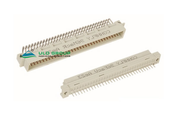
ULO-UD508 is a DIN 41612 R type connector with 2.54mm contact pitch and three available row locations, a, b and c. The illustrated assembly pairs a vertical female connector with a right-angle male connector. Two body sizes and selectable contact populations provide different row and column arrangements.
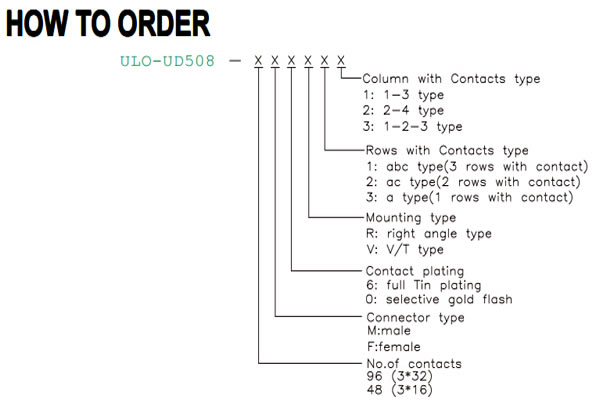
| Ordering field | Selection |
|---|---|
| Position size | 96: 3 × 32 locations; 48: 3 × 16 locations |
| Connector type | M: male; F: female |
| Contact plating | 6: full tin plating; 0: selective gold flash |
| Mounting type | R: right-angle; V: vertical |
| Rows with contacts | 1: abc, three populated rows; 2: ac, two populated rows; 3: a, one populated row |
| Column pattern | 1: 1–3 pattern; 2: 2–4 pattern; 3: 1–2–3 consecutive pattern |
The 96 and 48 designations identify body locations. Actual fitted-contact count depends on the row and column selections. Use the mounting orientation shown for the selected gender when applying the outline and PCB layout; the dimensions do not establish every possible combination of ordering fields.
| Characteristic | UD508 |
|---|---|
| Rated current | 2A |
| Contact impedance | ≤20mΩ |
| Insulation impedance | 1000MΩ |
| Dielectric withstand test | 1000VAC RMS for 60s |
| Operating temperature | -55°C to +125°C |
| Recommended wave soldering | 260°C for 5–10s |
| Insulator | PBT, material group I |
| Material flammability grade | UL94V-0 |
| Contact material | Copper alloy |
The dielectric withstand condition does not specify a continuous working voltage.
The following nine arrangements apply to both the 96-location, 3 × 32 body and the 48-location, 3 × 16 body at 2.54mm pitch. The consecutive pattern fills the selected rows across consecutive columns. The 1–3 and 2–4 patterns select alternating columns; use the contact arrangement diagrams to identify the numbered end and row orientation.
| Populated rows | Row code | Column pattern | Column code |
|---|---|---|---|
| abc | 1 | 1–2–3 consecutive | 3 |
| 1–3 alternating | 1 | ||
| 2–4 alternating | 2 | ||
| ac | 2 | 1–2–3 consecutive | 3 |
| 1–3 alternating | 1 | ||
| 2–4 alternating | 2 | ||
| a | 3 | 1–2–3 consecutive | 3 |
| 1–3 alternating | 1 | ||
| 2–4 alternating | 2 |
Dimensions A, B, C and D below are in millimetres. Use the corresponding male or female drawing endpoints. B identifies the mounting-hole centre distance in the recommended PCB layout, and D identifies the first-to-last contact span within a row.
| Connector | Position size | A | B | C | D |
|---|---|---|---|---|---|
| Female | 96, 3 × 32 | 94.9 | 90.0 | 85.0 | 78.74 |
| 48, 3 × 16 | 54.9 | 50.0 | 44.26 | 38.10 | |
| Male | 96, 3 × 32 | 93.8 | 88.9 | 85.8 | 78.74 |
| 48, 3 × 16 | 53.26 | 48.26 | 44.7 | 38.10 |
| Outline or PCB reference | Dimension |
|---|---|
| Contact pitch | 2.54mm ±0.1mm |
| Adjacent-row spacing | 2.54mm |
| Outer-row span | 5.08mm |
| PCB contact-hole diameter | Ø1.00mm |
| PCB mounting-hole diameter | Ø2.80mm |
| Recommended PCB-layout tolerance | ±0.05mm |
| Female side references | 2.60mm and 0.6mm contact thickness |
| Female termination projection | 4.50mm |
| Female terminal width reference | 0.50mm |
| Male terminal width reference | 0.50mm ±0.1mm |
| Male side-profile references | 10.90mm overall horizontal reference, 7.50mm inner reference, 1.60mm offset and 3.1mm lower reference |
| Male contact thickness | 0.6mm |

