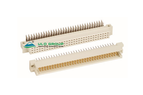

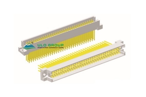
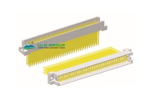
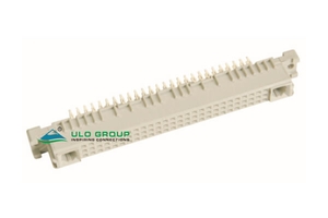
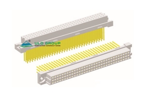
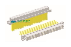
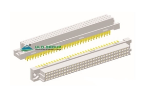
These DIN 41612 C type connectors use 2.54mm contact pitch. Select the model by gender, termination and tail length, then select the body size and populated rows. ULO-UD508A has a dedicated 78+2-contact arrangement and its own mounting pattern.
| Model | Gender and illustrated mounting | Termination | Position size | Tail projection |
|---|---|---|---|---|
| ULO-UD507 | Male vertical; female right-angle | Solder | 96 or 48 | Male 4.50mm; female follows the right-angle profile |
| ULO-UD507A | Male vertical | Press-fit | 96 or 48 | 4.50mm |
| ULO-UD507B | Male vertical | Straight solder tail | 96 or 48 | 13.00mm |
| ULO-UD507C | Male vertical | Press-fit | 96 or 48 | 13.0mm |
| ULO-UD507D | Male vertical | Press-fit | 96 or 48 | 17.0mm |
| ULO-UD508A | Female vertical | Press-fit | 78+2 | 4.50mm |
| ULO-UD508B | Female vertical | Straight solder tail | 96 or 48 | 13.0mm |
| ULO-UD508C | Female vertical | Press-fit | 96 or 48 | 13.0mm |
| ULO-UD508D | Female vertical | Press-fit | 96 or 48 | 17.0mm |
| ULO-UD508E | Female vertical | Press-fit | 96 or 48 | 4.5mm |
| Characteristic | All listed models |
|---|---|
| Rated current | 2A |
| Contact impedance | ≤20mΩ |
| Insulation impedance | 1000MΩ |
| Dielectric withstand test | 1000VAC RMS for 60s |
| Operating temperature | -55°C to +125°C |
| Insulator | PBT, material group I |
| Material flammability grade | UL94V-0 |
| Contact material | Copper alloy |
| Wave-soldering reference | 260°C for 5–10s |
Use the wave-soldering reference for solder assembly. It does not define a press-fit insertion process. For press-fit versions, use the exact model's PCB hole callouts and terminal geometry; insertion force and board-thickness limits are unspecified. The withstand test does not specify continuous working voltage.
For the 96/48 models, 96 denotes a 3 × 32-location body and 48 denotes a 3 × 16-location body. Actual fitted contacts depend on the selected rows and column pattern. UD508A instead orders position code 78 for the specified 78+2 arrangement, with row code 1 for abc and column code 3 for consecutive columns.
| Models | Gender code | Contact-plating choices | Additional ordering field |
|---|---|---|---|
| UD507 | M: male; F: female | 6: full tin; 0: selective gold flash | R: right-angle; V: vertical |
| UD507A, UD507C, UD507D | M: male | 6: full matt tin; 0: selective gold flash with nickel; C: selective 3µin gold with nickel; 1: selective 10µin gold with nickel | No separate mounting field listed |
| UD507B | M: male | 6: full tin; 0: selective gold flash; C: selective 3µin gold; 1: selective 10µin gold | No separate mounting field listed |
| UD508A | F: female | 6: full matt tin; 0: selective gold flash with nickel; C: selective 3µin gold with nickel; 1: selective 10µin gold with nickel | Fixed 78+2 arrangement |
| UD508B | F: female | 6: full tin; 0: selective gold flash; C: selective 3µin gold; 1: selective 10µin gold | No separate mounting field listed |
| UD508C, UD508D, UD508E | F: female | 6: full tin; 0: selective gold flash; C: selective 3µin gold with nickel; 1: selective 10µin gold with nickel | No separate mounting field listed |
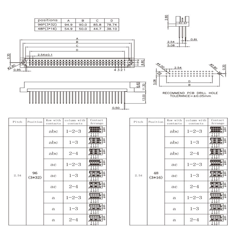
All 96/48 models offer the following nine contact arrangements for each body size. The numbered end and row orientation are shown in each model's drawing.
| Populated rows | Row code | Column pattern | Column code |
|---|---|---|---|
| abc, three rows | 1 | 1–2–3 consecutive | 3 |
| 1–3 alternating | 1 | ||
| 2–4 alternating | 2 | ||
| ac, two rows | 2 | 1–2–3 consecutive | 3 |
| 1–3 alternating | 1 | ||
| 2–4 alternating | 2 | ||
| a, one row | 3 | 1–2–3 consecutive | 3 |
| 1–3 alternating | 1 | ||
| 2–4 alternating | 2 |
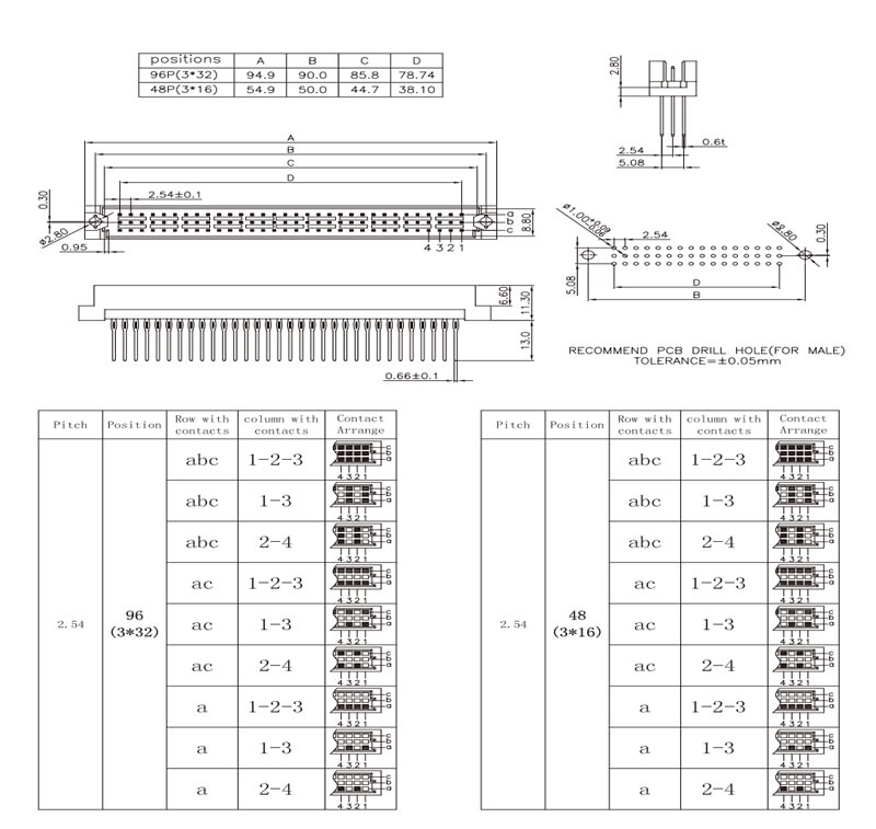
UD507 shows a vertical male and right-angle female configuration. The male tail-width reference is 0.50mm; the female reference is 0.50mm ±0.1mm. Keep the gender-specific A, B and C values separate.


UD507A has a 4.50mm tail projection and a 0.66mm terminal-width reference. Its pressure-contact region and PCB hole limits are shown in the drawing.


UD507B uses plain 0.50mm straight tails with 13.00mm projection. Its terminal shape and PCB layout differ from the 0.66mm press-fit versions.

Both models use a 0.66mm ±0.1mm terminal-width reference. UD507C has 13.0mm tails and UD507D has 17.0mm tails; their individual drawings retain the corresponding length and contact-pattern information.



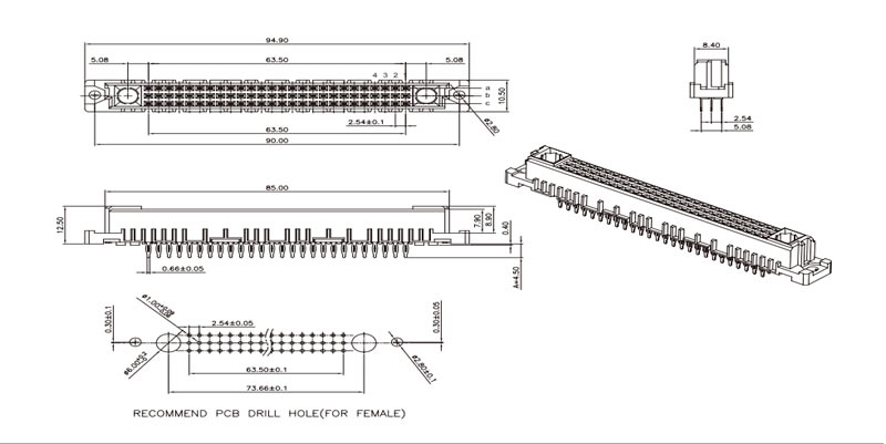
UD508A is a dedicated press-fit configuration. The 78+2 designation, its end features and its footprint must be selected together. The electrical role of the additional two positions is unspecified.
| UD508A drawing reference | Dimension |
|---|---|
| Overall length | 94.90mm |
| Mounting-centre reference | 90.00mm |
| Body length reference | 85.00mm |
| Contact-row span | 63.50mm |
| PCB contact-row span | 63.50mm ±0.1mm |
| PCB large-feature centres | 73.66mm ±0.1mm |
| PCB large-feature diameter | Ø6.00mm ±0.05mm |
| Adjacent-row spacing | 2.54mm |
| Outer-row span | 5.08mm |
| Contact pitch | 2.54mm ±0.1mm at the connector; 2.54mm ±0.05mm in the PCB pattern |
| End offset references | 5.08mm |
| Body width references | 10.50mm and 8.40mm at the shown endpoints |
| Height references | 12.50mm overall reference; 7.30mm and 9.00mm body references; 0.40mm lower offset |
| Tail projection / width | 4.50mm / 0.66mm ±0.05mm |

UD508B uses 13.0mm plain solder tails with a 0.50mm width reference. Its male-facing contact rows and numbered end are identified in the drawing.


These female models use a 0.66mm ±0.1mm terminal-width reference. Tail projections are 13.0mm for UD508C, 17.0mm for UD508D and 4.5mm for UD508E.

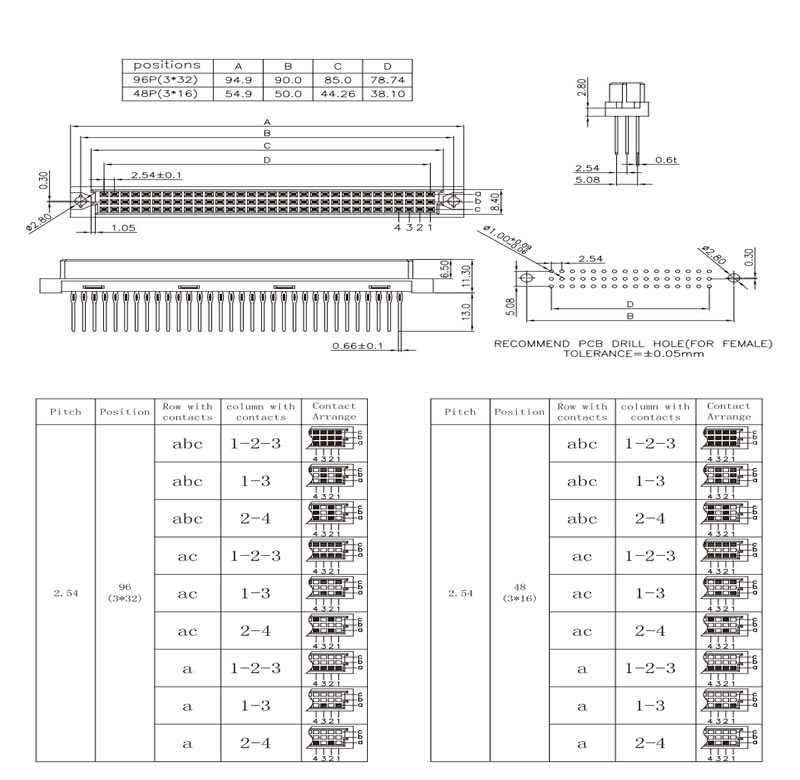


All A, B, C and D values below are in millimetres. B identifies mounting-hole centres, and D is the first-to-last contact span within a row. UD508A uses the separate dimensional section above.
| Models and gender | Position size | A | B | C | D |
|---|---|---|---|---|---|
| UD507 male; UD507A, UD507B, UD507C, UD507D | 96, 3 × 32 | 94.9 | 90.0 | 85.8 | 78.74 |
| 48, 3 × 16 | 54.9 | 50.0 | 44.7 | 38.10 | |
| UD507 female | 96, 3 × 32 | 93.8 | 88.9 | 85.0 | 78.74 |
| 48, 3 × 16 | 53.26 | 48.26 | 44.26 | 38.10 | |
| UD508B, UD508C, UD508D, UD508E | 96, 3 × 32 | 94.9 | 90.0 | 85.0 | 78.74 |
| 48, 3 × 16 | 54.9 | 50.0 | 44.26 | 38.10 |
These 96/48 bodies use 2.54mm adjacent-row spacing and a 5.08mm outer-row span, with Ø2.80mm mounting holes. The solder versions show Ø1.00mm PCB contact holes and a general layout tolerance of ±0.05mm. Press-fit drawings include additional hole-size limits that must be applied to the exact model. Main connector views mark contact pitch as 2.54mm ±0.1mm.
