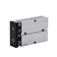
| Part Number: | TN | 25 | x | 20 |
|---|---|---|---|---|
| Explanation: |
Series TN - Double-acting twin-rod pneumatic cylinder |
Bore 10 - 10mm |
Stroke 10, 20, 30, 40, 50, 60, 70 - Standard strokes in mm for 10mm bore |
TN cylinders use two parallel rods connected to a common moving plate. Select bore and stroke for the required travel, then match the port and mounting layout. The ordering example TN25x20 denotes a 25mm bore and 20mm stroke.
| Ordering field | Example | Meaning |
|---|---|---|
| Series | TN | Double-acting twin-rod cylinder |
| Bore × stroke | 25×20 | 25mm bore × 20mm stroke |

| Parameter | 10mm | 16mm | 20mm | 25mm | 32mm |
|---|---|---|---|---|---|
| Action | Double acting | ||||
| Medium | Clean air filtered through a 40μm element | ||||
| Operating pressure | 0.1–0.9MPa | ||||
| Proof pressure | 1.35MPa | ||||
| Temperature | -5–70°C | ||||
| Cushioning | Bumper cushioning | ||||
| Port size | M5×0.8 | PT1/8 | |||
| Body material | Aluminum alloy | ||||
Compare listed standard strokes with the separate allowable and maximum stroke limits. The allowable-stroke figure is a travel limit, not a dimensional tolerance.
| Bore (mm) | Standard strokes (mm) | Allowable stroke (mm) | Maximum stroke (mm) | Switch option |
|---|---|---|---|---|
| 10 | 10, 20, 30, 40, 50, 60, 70 | 70 | 100 | CS1-G |
| 16 | 10, 20, 30, 40, 50, 60, 70, 80, 90, 100, 125, 150 | 150 | 200 | |
| 20 | 10, 20, 30, 40, 50, 60, 70, 80, 90, 100, 125, 150 | 150 | 200 | |
| 25 | 10, 20, 30, 40, 50, 60, 70, 80, 90, 100, 125, 150 | 150 | 200 | |
| 32 | 10, 20, 30, 40, 50, 60, 70, 80, 90, 100, 125, 150 | 150 | 200 |
Dimensions are in millimeters. Use A, B, C and D with the stroke additions shown on the drawing; E changes with the stroke threshold.

| Bore | A | B | C | D |
|---|---|---|---|---|
| 10 | 58 | 12 | 46 | 10 |
| Stroke ≤ (mm) | 10 | 20 | 30 | 40 | 50 | 60 | 70 |
|---|---|---|---|---|---|---|---|
| E (mm) | 30 | 30 | 35 | 40 | 45 | 50 | 55 |

| Bore | A | B | C | D |
|---|---|---|---|---|
| 32 | 108 | 30 | 78 | 35 |
| Stroke ≤ (mm) | 10 | 20 | 30 | 40 | 50 | 60 | 70 | 80 | 90 | 100 | 125 | 150 | 175 |
|---|---|---|---|---|---|---|---|---|---|---|---|---|---|
| E (mm) | 45 | 50 | 55 | 60 | 65 | 70 | 75 | 80 | 85 | 95 | 102.5 | 115 | 122.5 |
The 175mm dimensional entry describes an extended-stroke configuration and does not change the 150mm allowable-stroke figure in the selection table.
