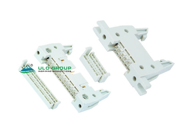

ULO-SH400 and ULO-SH403 use a two-row contact interface with 2.54mm longitudinal pitch and 2.54mm row spacing. The IDC cable and cover pitch is 1.27mm. SH400 adds long ejectors with two latch-height options; SH403 has a compact body and an optional strain-relief arrangement. Select the exact model, total contact count and mounting-hole configuration before sizing the cable assembly.
| Selection characteristic | SH400 | SH403 |
|---|---|---|
| Total contacts | 10, 14, 16, 24, 26, 30, 40, 50, 60, 64 | 10, 14, 16, 20, 24, 26, 30, 34, 40, 50, 60, 64 |
| Contact arrangement | Two rows, 2.54mm × 2.54mm | Two rows, 2.54mm × 2.54mm |
| Cable and cover pitch | 1.27mm | 1.27mm |
| Ejector | L: long | No ejector option listed |
| Latch dimension H | 8: 8.00mm standard; 4: 4.60mm special | Not applicable to the illustrated body |
| Screw-hole option | M: with; N: without | M: with; N: without |
| Strain relief | N: without | M: with; N: without |
| Contact plating | O: selective gold flash | O: selective gold flash |
| Housing colour | A: grey; B: black | A: grey; B: black |
The ordering fields differ between models. SH400 does not list 20- or 34-contact versions, and its strain-relief field lists only N. The screw-hole option identifies the housing configuration; screw size and supplied fastening hardware are unspecified.


| Characteristic | Both models |
|---|---|
| Insulation resistance | ≥1000MΩ |
| Contact impedance | ≤20mΩ |
| Dielectric withstand test | 500VAC for 1 minute |
| Operating temperature | 0°C to +85°C |
| Storage temperature | -20°C to +70°C |
| Insulator | Thermoplastic, material group I |
| Material flammability grade | UL94V-0 |
| Contact material | Copper alloy |
The 500VAC value is a dielectric test condition. Rated current, continuous working voltage and permissible conductor size are unspecified.
For both models, N is half the total contact count and A = (N−1) × 2.54mm. A is the first-to-last contact span within one mating row. Use the illustrated endpoints for each additional length; the cover pitch and mating-contact pitch describe different parts of the assembly.
| SH400 drawing reference | Dimension |
|---|---|
| Mating pitch and row spacing | 2.54mm ±0.1mm |
| Body length reference | A + 21.32mm ±0.5mm |
| Body width | 8.00mm |
| Full illustrated height | 30.4mm |
| Body height reference | 19.2mm |
| Lower profile references | 4.0mm and 5.2mm, at the separate endpoints shown |
| Internal vertical reference | 2.50mm |
| Mounting-slot opening | 3.20mm |
| Mounting-end length reference | 6.30mm |
| End references in front view | 4.90mm and 8.25mm |
| Standard / special latch H | 8.00mm / 4.60mm |
| Cover contact span | A + 1.27mm |
| Cover length | A + 7.02mm |
| Cover pitch | 1.27mm ±0.1mm |
| Cover plan width / outer side width | 6.30mm / 8.00mm |
| Cover side-height reference | 3.90mm |

| SH403 drawing reference | Dimension |
|---|---|
| Mating pitch and row spacing | 2.54mm ±0.1mm |
| Body and cover length | A + 12.98mm ±0.5mm |
| Body and cover width | 8.30mm |
| Body height reference | 10.00mm |
| Lower profile reference | 4.00mm |
| Side-view contact reference | 2.40mm |
| Mounting-slot opening | 3.20mm |
| Mounting-end length reference | 6.30mm |
| Cover contact span | A + 1.27mm |
| Cover pitch | 1.27mm |
| Cover height | 13.00mm |
| Cover internal height reference | 3.10mm |

