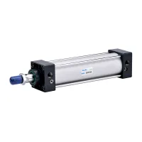

| Part Number: | SC | 50 | x | 50 | - | S | - | FA |
|---|---|---|---|---|---|---|---|---|
| Explanation: |
Series SC - Standard double-acting cylinder |
Bore 32 - 32mm |
Stroke 50 - 50mm; all listed bores |
Magnet Blank - Without magnet; omit S and its preceding separator |
Mounting Blank - Basic type; omit the mounting suffix and its separator |
The SC/SU family combines double-acting pneumatic cylinders with selectable rod arrangements, mounting styles and magnetic-piston options. SC uses the exposed tie-rod construction shown in the gallery; select the exact SC or SU body and mounting configuration when matching an existing installation. The second gallery view shows an adjustable-stroke double-rod configuration.
| Ordering field | Code | Selection |
|---|---|---|
| Family | SC / SU | Standard double acting |
| Rod arrangement | SCD | Double rod |
| Rod arrangement | SCJ | Double rod with adjustable stroke |
| Configuration | SCT | Multi-position |
| Bore and stroke | 50×50 | Example: 50mm bore × 50mm stroke |
| Magnet | Blank / S | Without magnet / with magnet |
| Mounting | Blank | Basic type |
| Mounting | CA / CB | Single ear / double ear |
| Mounting | FA / FB | Front flange / rear flange |
| Mounting | LB | Front and rear foot mounting |
| Mounting | TC / TC-M | Central trunnion / central trunnion with foot |
The selection example SC/SU50x50-S-FA denotes the chosen SC or SU family, 50mm bore, 50mm stroke, magnetic piston and front flange. The outline drawing also identifies SUD and SUJ counterparts to the double-rod and adjustable-stroke arrangements.
The operating ratings below cover 32–100mm bores. Larger bores in the dimensional and stroke tables do not extend these ratings automatically.
| Parameter | 32mm | 40mm | 50mm | 63mm | 80mm | 100mm |
|---|---|---|---|---|---|---|
| Action | Double acting | |||||
| Medium | Air filtered through a 40μm element | |||||
| Operating pressure | 0.1–0.9MPa | |||||
| Proof pressure | 1.35MPa | |||||
| Temperature | -5–70°C | |||||
| Cushioning | Adjustable cushioning | |||||
| Cushion stroke | 24mm | 32mm | ||||
| Port size | 1/8″ | 1/4″ | 3/8″ | 1/2″ | ||
| Body material | Aluminum alloy | |||||

Select the S magnetic-piston option for magnetic position sensing. Switches and their mounting bases are separate selection items.
| Bore (mm) | 32 | 40 | 50 | 63 | 80 | 100 | 125 | 160 |
|---|---|---|---|---|---|---|---|---|
| Switch options | CS1-F / CS1-U | |||||||
| Switch mounting base | F-50 | F-63 | F-100 | F-125 | F-160 | |||
Dimensions in this table are in millimeters. Listed standard strokes, the maximum standard stroke and the overall maximum stroke are separate selection limits.
| Bore | Listed standard strokes | Maximum standard stroke | Maximum stroke |
|---|---|---|---|
| 32 | 25, 50, 75, 100, 125, 150, 175, 200, 250, 300, 350, 400, 500 | 1000 | 2000 |
| 40 | 25, 50, 75, 100, 125, 150, 175, 200, 250, 300, 350, 400, 500, 600, 700, 800 | 1200 | 2000 |
| 50 | 25, 50, 75, 100, 125, 150, 175, 200, 250, 300, 350, 400, 500, 600, 700, 800, 900, 1000 | 1200 | 2000 |
| 63 | 25, 50, 75, 100, 125, 150, 175, 200, 250, 300, 350, 400, 500, 600, 700, 800, 900, 1000 | 1500 | 2000 |
| 80 | 25, 50, 75, 100, 125, 150, 175, 200, 250, 300, 350, 400, 500, 600, 700, 800, 900, 1000 | 1500 | 2000 |
| 100 | 25, 50, 75, 100, 125, 150, 175, 200, 250, 300, 350, 400, 500, 600, 700, 800, 900, 1000 | 1500 | 2000 |
| 125 | 25, 50, 75, 100, 125, 150, 175, 200, 250, 300, 350, 400, 500, 600, 700, 800, 900, 1000 | 1500 | 2000 |
| 160 | 25, 50, 75, 100, 125, 150, 175, 200, 250, 300, 350, 400, 500, 600, 700, 800, 900, 1000 | 1500 | 2000 |
Use the drawing for the chosen rod configuration. Standard length is A + stroke; double-rod length is A1 + 2 × stroke; adjustable double-rod length is A2 + 2 × stroke + adjustment. Linear values are in millimeters; K, L and O are thread designations. Unspecified values are shown as —.

| Bore | A | A1 | A2 | B | C | D | E | F | G | H | K | L | O | S | T | V |
|---|---|---|---|---|---|---|---|---|---|---|---|---|---|---|---|---|
| 32 | 140 | 187 | 182 | 47 | 93 | 28 | 32 | 15 | 27.5 | 22 | M10×1.25 | M6×1 | G1/8 | 45 | 33 | 12 |
| 40 | 142 | 191 | 185 | 49 | 93 | 32 | 34 | 15 | 27.5 | 24 | M12×1.25 | M6×1 | G1/4 | 50 | 37 | 16 |
| 50 | 150 | 207 | 196 | 57 | 93 | 38 | 42 | 15 | 27.5 | 32 | M16×1.5 | M6×1 | G1/4 | 62 | 47 | 20 |
| 63 | 152 | 209 | 199 | 57 | 95 | 38 | 42 | 15 | 27.5 | 32 | M16×1.5 | M8×1.25 | G3/8 | 75 | 56 | 20 |
| 80 | 183 | 258 | 243 | 75 | 108 | 47 | 54 | 21 | 33 | 40 | M20×1.5 | M10×1.5 | G3/8 | 94 | 70 | 25 |
| 100 | 189 | 264 | 249 | 75 | 114 | 47 | 54 | 21 | 33 | 40 | M20×1.5 | M10×1.5 | G1/2 | 112 | 84 | 25 |
| 125 | 251 | 357 | 348 | 106 | 145 | 60 | 74 | 32 | 40 | 54 | M27×2 | M12 | G1/2 | 140 | 110 | 32 |
| 160 | 312 | 444 | 441 | 132 | 180 | 65 | 94 | 38 | 50 | 72 | M36×2 | M16 | G1/2 | 180 | 140 | 40 |
| 200 | 347 | 509 | 472 | 162 | 185 | 75 | 112 | 50 | 50 | 72 | M36×2 | M16 | G3/4 | 220 | 175 | 40 |
| 250 | 384 | — | — | 189 | 195 | 95 | 119 | 70 | 50 | 84 | M42×2 | M20 | G3/4 | 280 | 225 | 50 |
Use the dimensional entries for 125–250mm bores only for the stated outlines; select pressure, temperature, stroke availability and accessories for the exact large-bore configuration separately.
