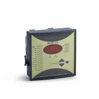

RPCF controllers calculate capacitor switching demand from the fundamental-frequency reactive power of the electrical system. They display both total and fundamental power factor, together with voltage and current distortion, and provide automatic or manual capacitor control. RPCFC versions add an RS485 interface using MODBUS-RTU for connection to a monitoring system.
The controller provides up to 16 outputs and 12 selectable output codes. Digital settings are retained after loss of power. Protection functions include overvoltage, undervoltage and excessive voltage harmonic distortion.
| Parameter | Specification |
|---|---|
| Rated voltage versions | 380V, 220V or 110V, ±10% |
| Rated current input | 5A |
| Frequency | 45-65Hz |
| Power factor display endpoints | 0.001 lagging to 0.001 leading |
| Reactive power range | 0-9999kvar |
| Active power range | 0-9999kW |
| Undervoltage protection versions | 300VAC or 180VAC |
| Output contact capacity | 220VAC, 7A |
| Sensitivity | 20mA |
| Current signal input resistance | ≤0.01Ω |
| Display | Four-digit red LED |
| Consumption | 10VA |
| Setting | Range or options |
|---|---|
| Operating mode | Automatic or manual |
| Power factor target | 0.70 inductive to 0.70 capacitive |
| Switching delay | 2-200s |
| Capacitor discharge period | 0-480s |
| Overvoltage setting | 400-450V line voltage; 230-265V phase voltage |
| Distortion setting | 0.1-30.0% |
| CT ratio | 50/5 to 4000/5 |
| C1 capacitor output | 0.1-100.0kvar |
| Output code | Pr-01 to Pr-12 |
| Output count | 1-16 circuits |
| Communication address | 1-255 on communication-equipped versions |
| Communication speed | 4800, 9600, 19200 or 115200 on communication-equipped versions |
| Panel dimensions (mm) | Cutout dimensions (mm) |
|---|---|
| 144×144 | 138×138 |
| 122×122 | 113×113 |
| 170×110 | 162×102 |
Mounting is available as a plug-in arrangement secured by retaining screws or a rail arrangement. Match the voltage version, protection thresholds, output count and panel size when selecting a controller.


