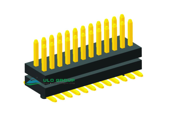
ULO-PH419ZC combines two rows of male contacts with two insulating spacers and SMT solder tails. Longitudinal contact pitch is 0.8mm; spacing between rows is 1.20mm ±0.1mm. The ordering range is 2 × 2 to 2 × 40 contacts, equivalent to 4 to 80 total contacts. Select locating-post and pickup-support options for the intended PCB and assembly process.
| Characteristic | PH419ZC |
|---|---|
| Mounting | SMT |
| Longitudinal pitch | 0.80mm ±0.1mm |
| Row spacing | 1.20mm ±0.1mm |
| Contact arrangement | Two rows, 2 to 40 positions per row |
| Contact section | 0.30mm square |
| Rated current | 1A |
| Contact impedance | ≤20mΩ |
| Insulation resistance | ≥500MΩ |
| Dielectric withstand test | 600VAC for 1 minute |
| Operating temperature | -45°C to +110°C |
The dielectric test is not a continuous working-voltage rating. Working voltage and storage temperature are unspecified.
| Item | Material or code |
|---|---|
| Insulator | Glass-filled PA46, material group I |
| Material flammability grade | UL94V-0 |
| Contact material | Copper alloy |
| Connector type | P: plug |
| Contact plating | 8: full gold flash |
| Housing colour | B: black |
| Mounting type | S: SMT |
| Dimension type | 1 |
| Pickup support | S: with pickup support; X: without pickup support |
| Packing | T: tray; R: tape on reel; B: tube |
| Post support | S: with post; X: without post |
The material grade does not establish a product certification. Pickup-support geometry and soldering-process limits are unspecified; do not derive a reflow profile from the operating-temperature range.

Dimensions A, B, C and D use the endpoints shown in the side view. B is a spacer reference, C is the transverse terminal spread, and D identifies the solder-tail offset. These values do not establish the completed board-to-board separation without the mating connector and PCB arrangement.
| Dimension type | A | B | C | D |
|---|---|---|---|---|
| 1 | 2.80mm | 2.35mm | 4.70mm | 0.35mm |
| Drawing reference | Value |
|---|---|
| Insulator width | 3.05mm |
| Height of each insulator | 1.00mm |
| Longitudinal body length | N × 0.8mm + 0.26mm |
| First-to-last contact span | (N−1) × 0.8mm |
| Illustrated post-centre spacing | (N−2) × 0.8mm |
| Locating-post diameter | Ø0.65mm |
| Locating-post projection shown | 1.00mm |
| PCB locating-hole diameter | Ø0.90mm |
| SMT pad width | 0.50mm |
| Inner transverse pad gap | 1.70mm |
| Overall transverse pad envelope | C ±0.1mm, with C = 4.70mm |
| Recommended PCB-layout tolerance | ±0.05mm unless separately specified |
N is the number of positions per row, or half the total contacts. Under the illustrated post-spacing formula, two distinct post locations require N greater than 2; the post arrangement at the minimum 2 × 2 size is unspecified. Check the selected count and post configuration against the PCB layout.

