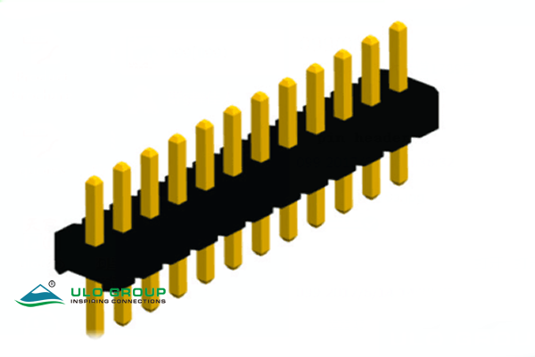
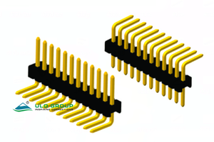
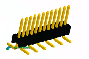
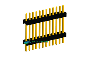

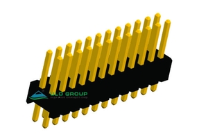



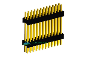
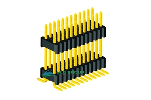
PH419A through PH419L provide male pin connections on a 1.27mm longitudinal grid. Choose the row count, terminal direction, housing height and spacer geometry as a complete configuration. Single-row types use one contact per longitudinal position; dual-row types have two contacts per position.
PH419L combines 1.27mm longitudinal pitch with 2.54mm spacing between rows. The other dual-row models use 1.27mm row spacing. Equal longitudinal pitch alone does not establish mating or PCB interchangeability.
| Model | Rows × positions per row | Termination | Construction | Housing-height options |
|---|---|---|---|---|
| ULO-PH419A | 1 × 1 to 1 × 40 | Vertical through-hole | Single insulator | 1.00mm, 1.50mm, 2.00mm |
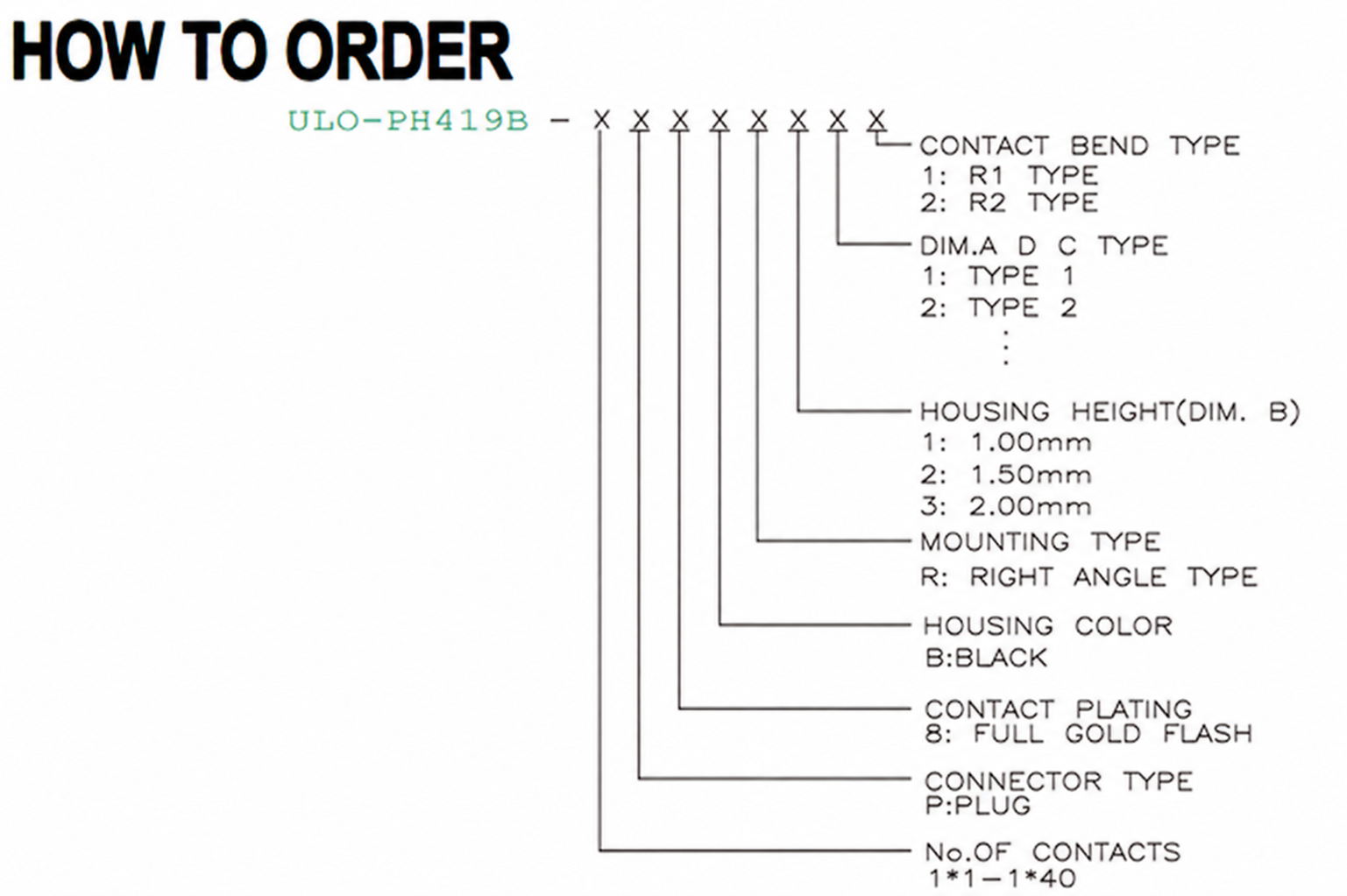
| ULO-PH419B | 1 × 1 to 1 × 40 | Right-angle through-hole, R1 or R2 | Single insulator | 1.00mm, 1.50mm, 2.00mm |
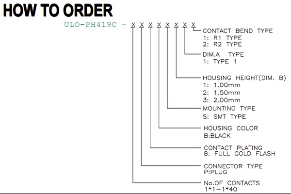
| ULO-PH419C | 1 × 1 to 1 × 40 | SMT, alternating R1 or R2 bends | Single insulator | 1.00mm, 1.50mm, 2.00mm |
| ULO-PH419D | 1 × 1 to 1 × 40 | Vertical through-hole | Two spacer insulators | 1.00mm, 1.50mm, 2.00mm |
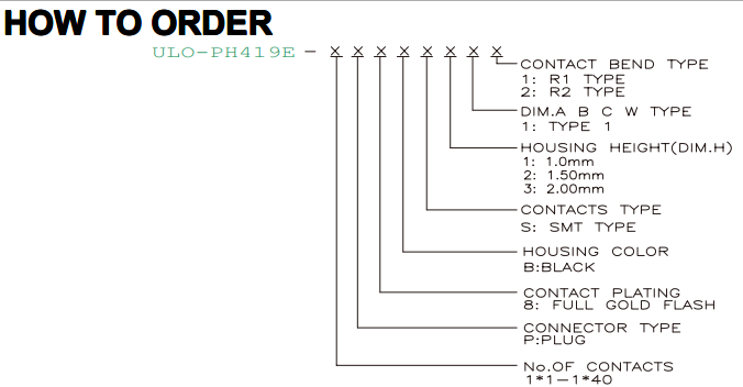
| ULO-PH419E | 1 × 1 to 1 × 40 | SMT, alternating R1 or R2 bends | Two spacer insulators | 1.00mm, 1.50mm, 2.00mm |
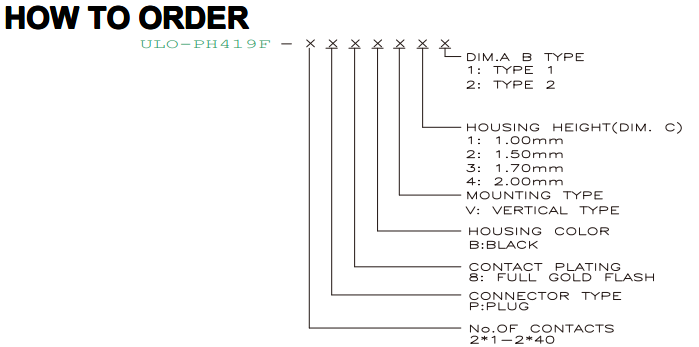
| ULO-PH419F | 2 × 1 to 2 × 40 | Vertical through-hole | Single insulator | 1.00mm, 1.50mm, 1.70mm, 2.00mm |
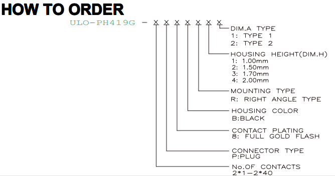
| ULO-PH419G | 2 × 1 to 2 × 40 | Right-angle through-hole | Single insulator | 1.00mm, 1.50mm, 1.70mm, 2.00mm |
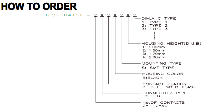
| ULO-PH419H | 2 × 1 to 2 × 40 | SMT | Single insulator | 1.00mm, 1.50mm, 1.70mm, 2.00mm |
| ULO-PH419I | 2 × 1 to 2 × 40 | SMT with locating feature | Single insulator | 1.00mm, 1.50mm, 1.70mm, 2.00mm |
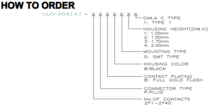
| ULO-PH419J | 2 × 1 to 2 × 40 | SMT | Two spacer insulators | 1.00mm, 1.50mm, 1.70mm, 2.00mm |
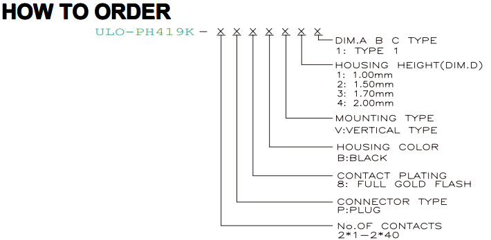
| ULO-PH419K | 2 × 1 to 2 × 40 | Vertical through-hole | Two spacer insulators | 1.00mm, 1.50mm, 1.70mm, 2.00mm |
| ULO-PH419L | 2 × 3 to 2 × 40 | SMT | Two spacer insulators; 2.54mm row spacing | 2.54mm |
| Characteristic | Value |
|---|---|
| Rated current | 1A |
| Insulation resistance | ≥500MΩ |
| Contact impedance | ≤20mΩ |
| Dielectric withstand test | 600VAC for 1 minute |
| Contact material | Copper alloy |
| Contact finish | Full gold flash |
| Insulation | PA46, material group I |
| Material flammability grade | UL94V-0 |
| Housing colour | Black |
| Models | Operating temperature |
|---|---|
| PH419A, PH419B, PH419C | -45°C to +110°C |
| PH419D, PH419E, PH419F | -45°C to +105°C |
| PH419G, PH419H, PH419I, PH419J, PH419K, PH419L | -40°C to +105°C |
The withstand test does not define a continuous working voltage. Working-voltage and storage-temperature ratings are unspecified. Material flammability classification does not establish product certification. Contact count, thermal conditions and mating geometry must be considered for the intended assembly.
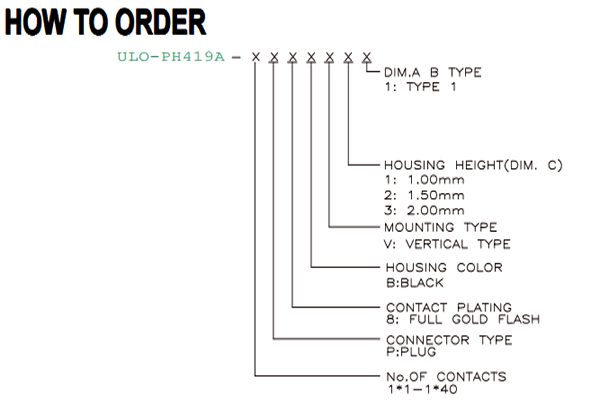
The model code selects the terminal arrangement. P identifies a plug where that field is shown, 8 identifies full gold flash, and B identifies a black housing. Mounting codes are V for vertical through-hole, R for right angle and S for SMT. The individual ordering diagrams define which fields apply to each model.
| Models | Housing-height codes | Additional selection |
|---|---|---|
| PH419A through PH419E | 1: 1.00mm; 2: 1.50mm; 3: 2.00mm | PH419B, PH419C and PH419E: bend code 1 for R1 or 2 for R2 |
| PH419F through PH419K | 1: 1.00mm; 2: 1.50mm; 3: 1.70mm; 4: 2.00mm | Choose the model-specific dimension type |
| PH419L | 5: 2.54mm | Dimension type 1 |
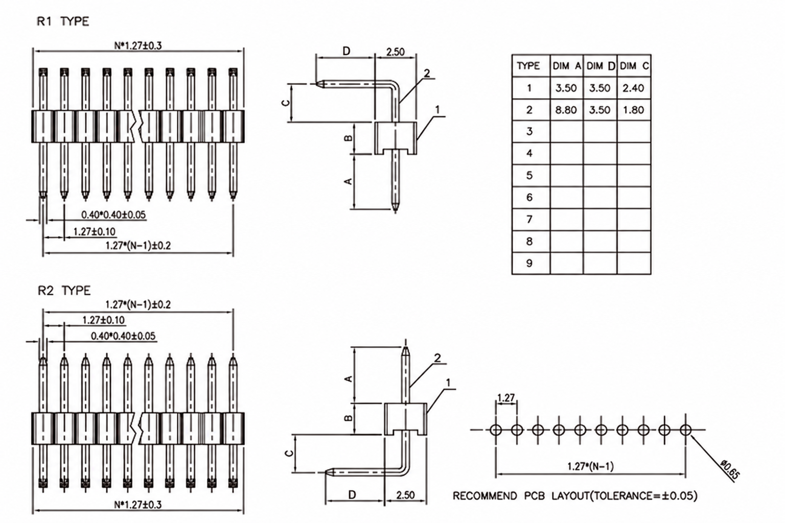
Dimensions below are in mm. Letter definitions belong to the adjacent model drawing and must not be transferred between models. N is the number of contacts for a single row and half the total contact count for two rows. The nominal first-to-last contact span is (N−1) × 1.27mm. For SMT versions, pad width, pad-row separation and locating holes remain model-specific. Housing height alone is not the completed board-to-board separation.
| Dimension type | A | B |
|---|---|---|
| 1 | 2.60 | 2.40 |
C is the separately selected housing height. The single-row footprint uses Ø0.65mm holes at 1.27mm pitch.

R1 and R2 place the bend on opposite sides of the insulator. Housing height B is selected independently; D identifies the horizontal projection in the side views.
| Dimension type | A | D | C |
|---|---|---|---|
| 1 | 3.50 | 3.50 | 2.40 |
| 2 | 8.80 | 3.50 | 1.80 |
| Dimension type | A |
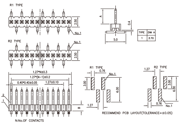
|---|---|
| 1 | 3.70 |
B is the selected housing height. The terminal spread is 5.0mm with a 0.4mm terminal section at the soldering end. R1 and R2 reverse the alternating pad sequence; both footprint views show 0.76mm-wide pads and a 6.0mm overall transverse pad envelope.
| Dimension type | A | B | C |
|---|---|---|---|
| 1 | 2.80 | 2.60 | 6.20 |
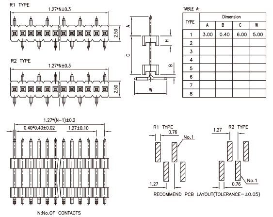
Two insulators locate the contacts along the spacer section. H is the chosen height of each insulator; C follows the endpoints shown in the side view. The PCB pattern uses Ø0.65mm holes.


| Dimension type | A | B | C | W |
|---|---|---|---|---|
| 1 | 3.00 | 0.40 | 6.00 | 5.00 |
H defines insulator height. R1 and R2 provide opposite alternating SMT bends with corresponding first-contact positions; W is the terminal spread.
| Dimension type | A | B |
|---|---|---|
| 1 | 3.70 | 2.10 |
| 2 | 3.50 | 3.50 |
C is the housing height. The body width is 3.40mm; the two rows are 1.27mm apart and use Ø0.65mm PCB holes.

| Dimension type | A | B | C |
|---|---|---|---|
| 1 | 2.70 | 2.50 | 1.60 |
| 2 | 3.80 | 2.00 | 2.50 |
H is the selected housing height. The PCB hole grid remains 1.27mm × 1.27mm with Ø0.65mm holes; use the side view to evaluate the bend clearance.

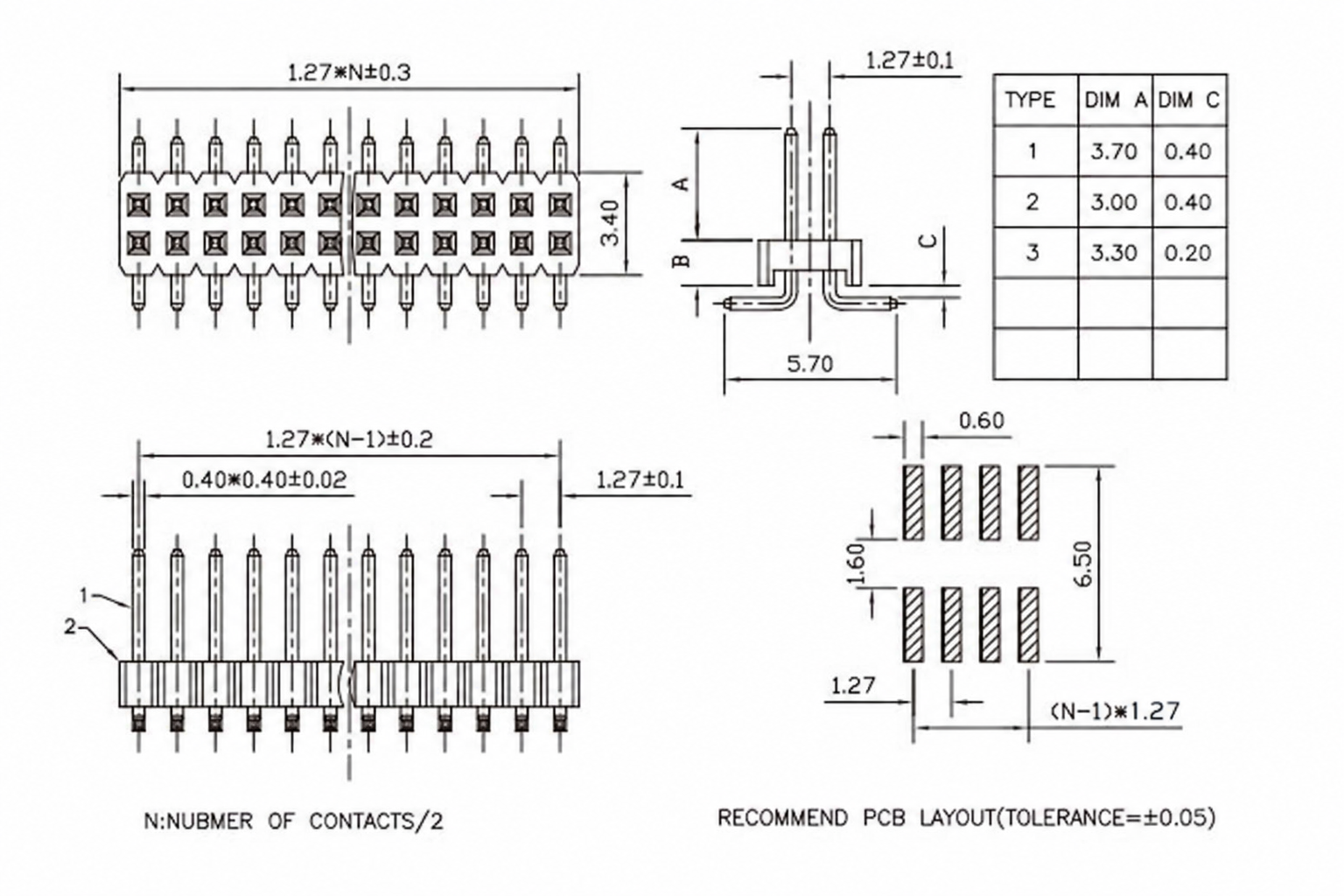
| Dimension type | A | C |
|---|---|---|
| 1 | 3.70 | 0.40 |
| 2 | 3.00 | 0.40 |
| 3 | 3.30 | 0.20 |
B is the housing height. The terminal spread is 5.70mm. The footprint shows 0.60mm-wide pads, a 1.60mm gap between the opposing pad ends and a 6.50mm overall transverse pad envelope. The longitudinal pad-centre span is (N−1) × 1.27mm.
| Dimension type | A | B | C |
|---|---|---|---|
| 1 | 3.00 | 5.50 | 0.60 |
| 2 | 3.70 | 5.70 | 0.60 |
H is the housing height. The footprint includes the locating hole shown at Ø0.80mm, 0.60mm-wide pads and a 6.40mm ±0.5mm transverse reference. Position the locating feature from the complete drawing.


| Dimension type | A | B | C | W |
|---|---|---|---|---|
| 1 | 3.00 | 0.70 | 6.00 | 5.50 |
Two insulators provide the spacer arrangement. H selects each insulator height. The pad layout uses 0.60mm-wide pads with a 6.00mm overall transverse envelope.

| Drawing dimension type | A | B | C |
|---|---|---|---|
| 1 | 3.00 | 2.30 | 6.00 |
| 2 | 4.00 | 3.00 | 15.00 |
The ordering diagram explicitly lists type 1; the dimension drawing also provides type 2 as a dimensional reference. Type 2 ordering availability is unspecified. H identifies insulator height; the ordering chart calls that height field D. The footprint uses two rows of Ø0.65mm holes at 1.27mm spacing.

| Dimension type | A | B | D | Housing height C |
|---|---|---|---|---|
| 1 | 9.46 | 1.27 | 3.00 | 2.54 |
This model starts at 2 × 3 contacts. Longitudinal pitch is 1.27mm and row spacing is 2.54mm. The terminal spread is 7.4mm; the footprint shows 0.60mm-wide pads, a 3.60mm inner gap and an 8.40mm overall transverse envelope.


