


| Part Number: | ULO | - | PH413H | - | 2 | * | 2 | P | 8 | B | S | R | S |
|---|---|---|---|---|---|---|---|---|---|---|---|---|---|
| Explanation: |
Code Prefix |
Model PH413A - Single-row vertical |
Rows 1 - PH413A, C or D |
Contacts per Row 2 - Two contacts per row; this breakdown is limited to this explicitly defined count |
Connector Type P - Plug; all covered models |
Contact Finish 8 - Full gold flash; all covered models |
Color B - Black |
Mounting or Pickup V - Vertical; PH413A or E |
Dimension or Packing 1 - PH413A A/B=4.00/2.80mm; C A/B/C=4.00/2.50/4.40mm; E A/B=2.80/4.00mm; F A/B/C=4.00/2.80/9.30mm; G A=4.00mm |
Contact Pattern or Posts 1 - PH413C R1 contact pattern |
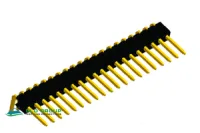
PH413A through PH413H provide male pin connections in vertical, right-angle and SMT configurations. Match the full suffix and its drawing to the mating height and board footprint. N in each dimensional drawing means contacts per row; the dual-row versions contain 2N contacts.
| Property | Applicable value |
|---|---|
| Rated current | 1.5A |
| Insulation resistance | ≥500MΩ |
| Contact resistance | ≤20mΩ |
| Dielectric withstand | 600VAC for 1 minute |
| PH413A, PH413B, PH413C operating temperature | -45°C to +110°C |
| PH413D, PH413E, PH413F, PH413G, PH413H operating temperature | Unestablished: -45°C to +110°C and -20°C to +80°C listed |
| Insulator | Thermoplastic; PH413G specifically lists PA46 |
| Material group / flammability | I / UL94V-0 |
| Contact material | Copper alloy |
The withstand test does not establish continuous working voltage. Storage temperature, UL use-group ratings and certification numbers are unspecified. Conflicting operating ranges do not define an approved temperature envelope.
| Model | Rows and mounting | Ordering options | Defined dimensions |
|---|---|---|---|
| PH413A | Single row, vertical through-hole | 1×2–1×X; P plug, B black, V vertical; finish 8 full gold flash or 6 tin | Five A/B types below |
| PH413B | Single row, right-angle through-hole | Exact order-code syntax and contact-count range unestablished | Six A/B/C and pin-length types below |
| PH413C | Single row, upright SMT; R1 and R2 pad patterns | 1×2–1×X; P plug, B black, S SMT, 8 full gold flash; contact type 1 R1 or 2 R2 | Type 1: A/B/C=4.00/2.50/4.40mm |
| PH413D | Single row, right-angle SMT | 1×2–1×X; B black, S SMT, 8 full gold flash; P plug is illustrated, S socket code is also listed without a socket drawing | A=4.00mm; bend reference 3.00mm |
| PH413E | Dual row, vertical through-hole | 2×2–2×X; P plug, B black, V vertical; 8 full gold flash or 6 tin | Seven A/B types below |
| PH413F | Dual row, right-angle through-hole | 2×2–2×X; P plug, B black, R right angle, 8 full gold flash | Two A/B/C types below |
| PH413G | Dual row, right-angle SMT | 2×2–2×X; P plug, B black, S SMT, 8 full gold flash | Type 1: A=4.00mm; bends referenced at 3.00/7.00mm |
| PH413H | Dual row, upright SMT | 2×2–2×X; P plug, B black, 8 full gold flash; pickup S with/X without; post S with/X without; packing A polybag/B tube/R tape and reel | 4.00mm contact projection, 2.00mm body height; pickup and posts affect outline |
X is an unspecified upper contact count; no maximum is assigned. PH413B's retained ordering illustration is labeled PH410 and describes SMT options, so those codes do not establish PH413B availability. PH413B's outline instead shows the right-angle through-hole arrangement used here.
| Model | Type | A, mm | B, mm |
|---|---|---|---|
| PH413A | 1 | 4.00 | 2.80 |
| 2 | 6.00 | 5.00 | |
| 3 | 2.80 | 10.20 | |
| 4 | 15.20 | ||
| 5 | 7.00 | 3.00 | |
| PH413E | 1 | 2.80 | 4.00 |
| 2 | 3.50 | 5.08 | |
| 3 | 10.00 | 2.00 | |
| 4 | 2.80 | 10.20 | |
| 5 | 4.00 | 8.00 | |
| 6 | 2.50 | 4.30 | |
| 7 | 2.80 | 3.90 |
Both outlines use 0.50×0.50mm contacts with ±0.05mm tolerance, 2N±0.3mm body length and 2(N−1)±0.2mm end-contact span. Body height is 2.00mm; body width is 2.00mm for PH413A and 4.00mm for PH413E. The recommended holes are Ø0.80mm. PH413E uses a 2.00mm square grid.


| Model / type | A/B/C, mm | Pin length, mm |
|---|---|---|
| PH413B / 1 | 4.00/2.80/1.00 | 10.50 |
| PH413B / 2 | 5.00/2.50/1.00 | 11.00 |
| PH413B / 3 | 5.00/4.75/0.75 | 13.10 |
| PH413B / 4 | 3.80/3.80/0.75 | 11.00 |
| PH413B / 5 | 2.50/2.80/1.30 | 9.20 |
| PH413B / 6 | 3.70/3.00/1.75 | 11.00 |
| PH413F / 1 | 4.00/2.80/9.30 | 10.70 / 14.70 |
| PH413F / 2 | 6.00/2.80/11.30 | 12.70 / 16.70 |
Use the dimension letters in the matching outline; A, B and C are not interchangeable between models. Both use Ø0.80mm PCB holes, 0.50mm square pins, 2N±0.3mm body length and 2(N−1)±0.2mm span. PH413F has 2.00mm contact-row spacing.


| Model | Footprint and mechanical references |
|---|---|
| PH413C | 2.00mm body height; 0.50mm square contacts; R1/R2 alternating pads 0.80×1.50mm with 5.40mm outside reference |
| PH413D | 2.00mm body height and width; pads 0.80×1.50mm in one row at 2.00mm pitch |
| PH413G | 4.00mm body width; 0.50mm square contacts; pads 0.80×1.50mm, 4.00±0.1mm outside row reference |
| PH413H | 4.00mm contact projection; 6.20mm foot span; 0.64mm post and Ø0.80mm locating hole; pads 0.90×2.50mm, 7.00mm outside reference; pickup 8.00mm across one view and 6.00mm across the side view |


