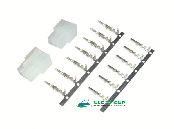
ULO-PCB461B provides 4.2mm-pitch crimp connector components in two-row and three-row arrangements. Each arrangement has male and female housings with separate corresponding crimp contacts.
| Arrangement | Ordering range | Total contacts | Components |
|---|---|---|---|
| Two rows | 2 × 2 to 2 × 10 | 4–20 | Male housing, female housing, male contact and female contact |
| Three rows | 3 × 2 to 3 × 10 | 6–30 | Male housing, female housing, male contact and female contact |
The first ordering number is the number of rows and the second is the contacts per row. Specify housing gender, row arrangement and terminal quantities separately. A complete cable assembly, cable length and PCB header are unspecified for this model.
| Characteristic | PCB461B |
|---|---|
| Rated current | 3A |
| Rated voltage | 250V |
| Core wire range | 24–18AWG |
| Contact impedance | ≤30mΩ |
| Insulation impedance | ≥1000MΩ |
| Dielectric withstand test | 500VAC for 1 minute |
| Operating temperature | -45°C to +110°C |
| Storage temperature | -25°C to +85°C |
| Thickness reference | 1.6mm |
| Insulator | Nylon 66, material group I |
| Material flammability grade | UL94V-0 |
| Contact material | Copper alloy |
The thickness reference does not define a PCB mounting interface for these cable housings. Wire-insulation diameter, stripping length and crimp tooling are unspecified.
| Field | Code and meaning |
|---|---|
| Rows and contacts per row | 2 × 2–10 or 3 × 2–10 |
| Connector type | M: male; F: female |
| Termination | C: crimp |
| Housing colour | T: transparent |
| Contact plating | 6: tin; 8: full gold flash |

N is the number of contacts per row. The longitudinal contact span is (N − 1) × 4.20mm and the housing body row length is N × 4.20mm + 1.3mm. Row spacing is 4.20mm; the first-to-third-row span is 8.40mm for three-row housings.
| Housing | Longitudinal side-profile reference | Additional profile references |
|---|---|---|
| Male, two rows | 23.90mm | 9.60mm body width; 11.60mm outer side width; 12.00mm latch-region reference |
| Male, three rows | 23.90mm | 13.80mm body width; 15.80mm outer side width; 12.00mm latch-region reference |
| Female, two rows | 19.60mm | 9.00mm inner longitudinal reference |
| Female, three rows | 19.60mm | 9.00mm inner longitudinal reference |
Male and female mating-face views use different viewing directions and contact-number layouts. Use the labelled gender drawing when assigning positions.
The male contact strip has 11.00mm carrier pitch and Ø1.50mm carrier holes; its illustrated profile includes 20.80mm and 16.78mm longitudinal references, a 1.14mm contact tip width and a 3.20mm front-profile width. The female strip has 10.00mm carrier pitch and Ø1.50mm carrier holes, with 18.15mm and 14.60mm longitudinal references, a 1.70mm tip-region width and a 3.00mm front-profile width.
Male A–A crimp-section references are 3.70mm wide and 4.40mm high; female A–A references are 3.70mm wide and 4.00mm high. Both B–B sections show 2.20mm width and 2.40mm height. These outline references describe the illustrated contact geometry; use the complete drawing for their measurement endpoints.

