ULO-PCB457 is a 2.5mm-pitch XH connector system with 2 to 20 positions. Select the female cable housing, female crimp terminals and male PCB header as separate components. Male headers are illustrated in vertical and right-angle forms with selectable contact kink.
Component
Selection
Female housing
2–20 positions; white or transparent
Female crimp terminal
28–22AWG wire; tin or full gold-flash finish
Male PCB header
2–20 positions; vertical or right-angle; with or without kink
PCB457 identifies the family. Individual component suffix numbers and package quantities are unspecified. Specify the housings, terminals and headers needed for the intended assembly.
Ratings, materials and wire selection
Characteristic
PCB457
Rated current
1A
Rated voltage
250V
Contact impedance
≤30mΩ
Insulation impedance
≥1000MΩ
Dielectric withstand test
500VAC for 1 minute
Operating temperature
-25°C to +85°C
Storage temperature
-25°C to +85°C
Board thickness reference
1.6mm
Insulator
Nylon 66, material group I
Material flammability grade
UL94V-0
Contact material
Copper alloy
Terminal conductor area
Wire gauge
Wire outside diameter
0.08–0.33mm²
28–22AWG
1.2–1.9mm
Ordering fields
Field
Code and meaning
Contact count
2–20
Connector type
M: male; F: female
Termination or mounting
C: crimp; V: vertical; R: right-angle
Housing colour
W: white; T: transparent
Contact plating
6: tin; 8: full gold flash
Contact form
S: with kink; X: without kink
The crimp option describes the female terminal. Vertical and right-angle options describe the male PCB header. Select each field for its applicable component.
PCB457 ordering options for cable and PCB components.
Female housing and male header dimensions
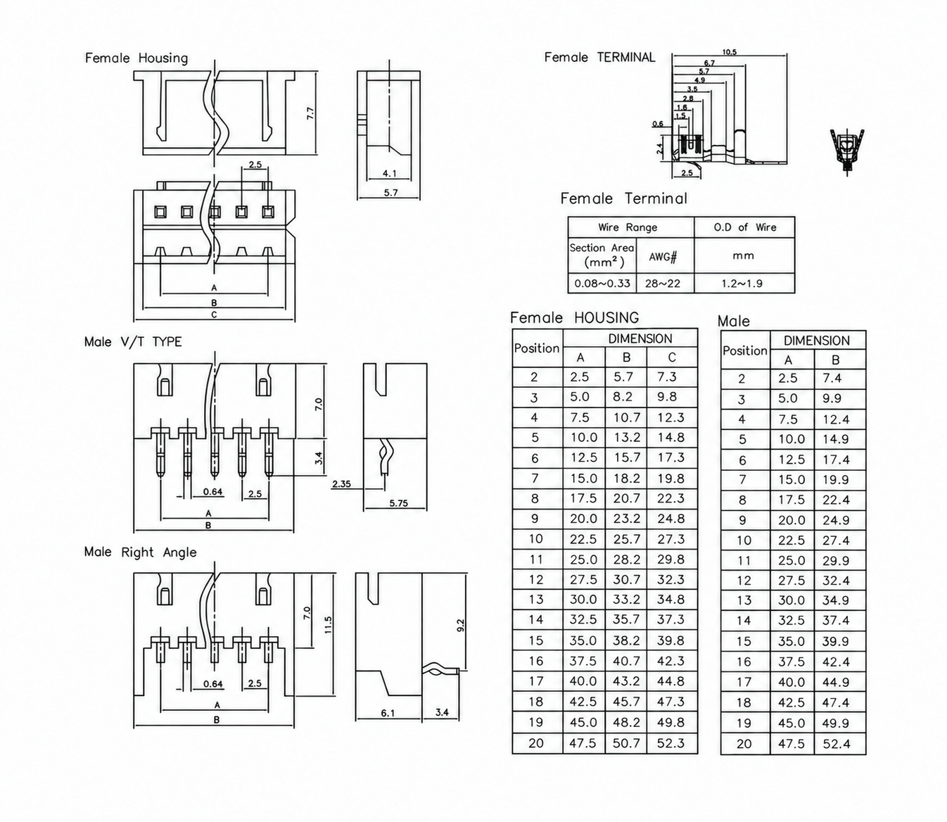
A is the first-to-last contact span. The female housing has separate B and C length references; the male header uses its own B dimension. All values in the table are in millimetres.
Positions
Female A
Female B
Female C
Male A
Male B
2
2.5
5.7
7.3
2.5
7.4
3
5.0
8.2
9.8
5.0
9.9
4
7.5
10.7
12.3
7.5
12.4
5
10.0
13.2
14.8
10.0
14.9
6
12.5
15.7
17.3
12.5
17.4
7
15.0
18.2
19.8
15.0
19.9
8
17.5
20.7
22.3
17.5
22.4
9
20.0
23.2
24.8
20.0
24.9
10
22.5
25.7
27.3
22.5
27.4
11
25.0
28.2
29.8
25.0
29.9
12
27.5
30.7
32.3
27.5
32.4
13
30.0
33.2
34.8
30.0
34.9
14
32.5
35.7
37.3
32.5
37.4
15
35.0
38.2
39.8
35.0
39.9
16
37.5
40.7
42.3
37.5
42.4
17
40.0
43.2
44.8
40.0
44.9
18
42.5
45.7
47.3
42.5
47.4
19
45.0
48.2
49.8
45.0
49.9
20
47.5
50.7
52.3
47.5
52.4
Component profile
Dimensions and references
Female housing
7.7mm height; 5.7mm overall side width; 4.1mm inner width
Female terminal
10.5mm overall length; reference chain 6.7mm, 5.7mm, 4.9mm, 3.5mm, 2.8mm, 1.8mm and 1.5mm; 0.6mm, 2.4mm and 2.5mm detail references
Vertical male header
7.0mm body height; 3.4mm tail projection; 5.75mm side width; 2.35mm contact offset; 0.64mm contact-width reference
Right-angle male header
7.0mm body reference; 11.5mm overall front reference; 9.2mm side reference; 6.1mm side-body length; 3.4mm tail projection; 0.64mm contact-width reference
PCB457 female housing and crimp terminal, vertical and right-angle male headers, and position-specific dimensions.