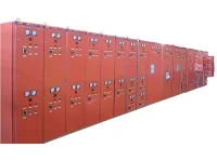
This motor control center example was developed for a sewage-treatment installation with two plant sections sharing one panel. The panel arrangement, feeder schedule, controls and section isolation describe that project configuration; they are not universal ratings.
Project configuration example
Panel dimensions of 8000×2000×600mm for the documented arrangement.
Sixteen 55kW motors with variable-speed drives, four 7.5kW motors with drives and four 5kW motors with drives.
2000A incomer circuit breaker, 2400A isolator, separate breakers for the two plant sections, RAS/WAS isolator and distribution board.
The layout and circuit drawings show one project configuration. A new MCC must be based on its own motor list, fault level, supply, control philosophy, enclosure conditions and applicable standards.
Drawings and connection details
MCC section layout and feeder arrangement drawing.MCC front elevation with incoming, VFD and distribution sections.MCC feeder schedule and equipment allocation table.MCC compartment arrangement for incomer, drive feeders and spare sections.MCC full-width front elevation and section dimensions.MCC control-panel layout with local and remote operating sections.