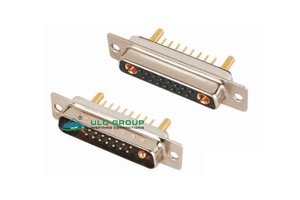
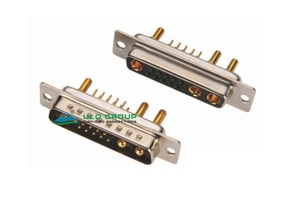
| Part Number: | ULO | - | MP421A | - | M | B | N | 8 | 4 |
|---|---|---|---|---|---|---|---|---|---|
| Explanation: |
Brand ULO - ULO |
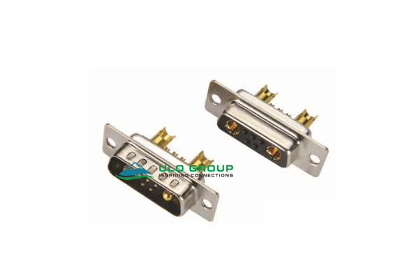
Model MP421A - 7W2; solder cup |
Connector Type M - Male |
Colour B - Black |
Shell Plating N - Front shell nickel plated; back shell tin plated |
Contact Plating 8 - Full gold flash |
Power-contact Current 1 - 10A; MP421A, MP421B and MP421C only |
These machined-contact D-sub connectors combine signal and power circuits in one interface. Select the contact layout and termination style together. Each model is available with male or female contacts.
| Model | Layout | Signal contacts | Power contacts | Termination | Power-contact rating |
|---|---|---|---|---|---|
| ULO-MP421A | 7W2 | 5 | 2 | Solder cup | 10A, 20A, 30A or 40A |
| ULO-MP421B | 17W2 | 15 | 2 | Solder cup | 10A, 20A, 30A or 40A |
| ULO-MP421C | 13W3 | 10 | 3 | Solder cup | 10A, 20A, 30A or 40A |
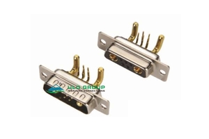
| ULO-MP422D | 7W2 | 5 | 2 | Right-angle PCB | 40A |
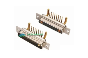
| ULO-MP422E | 17W2 | 15 | 2 | Right-angle PCB | 40A |
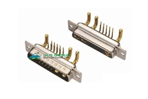
| ULO-MP422F | 13W3 | 10 | 3 | Right-angle PCB | 40A |
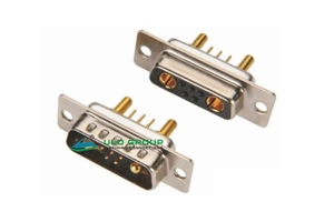
| ULO-MP422M | 7W2 | 5 | 2 | Straight through-hole PCB | 40A |
| ULO-MP422N | 17W2 | 15 | 2 | Straight through-hole PCB | 40A |
| ULO-MP422O | 13W3 | 10 | 3 | Straight through-hole PCB | 40A |
The layout number includes both contact types: 7W2 has seven total contacts, 17W2 has seventeen and 13W3 has thirteen. Signal-contact rating is 5A for all nine models. Apply power-contact ratings to the selected power-contact version.
| Characteristic | All nine models |
|---|---|
| Signal-contact rated current | 5A |
| Rated voltage | 300V |
| Insulation resistance | ≥1000MΩ |
| Contact impedance | ≤20mΩ |
| Dielectric withstand test | 500VAC for 1 minute |
| Operating temperature | -45°C to +110°C |
| Durability | 500 cycles |
| Retention | ≥1000gf |
| Insulator | PBT with 30% glass fibre, material group I |
| Material flammability grade | UL94V-0 |
| Contact material | Copper alloy |
| Shell material | Steel |
The dielectric withstand voltage is a test condition. Wire gauge, soldering process limits and circuit-level current derating conditions are unspecified.
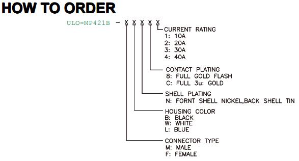
| Field | Code and meaning | Applicable models |
|---|---|---|
| Connector type | M: male; F: female | All nine models |
| Insulator colour | B: black; W: white; L: blue | All nine models |
| Shell plating | N: nickel front shell, tin back shell | All nine models |
| Contact plating | 8: full gold flash; C: full 3µin gold | All nine models |
| Power-current code | 1: 10A; 2: 20A; 3: 30A; 4: 40A | MP421A, MP421B and MP421C only |
MP421A, MP421B and MP421C use the same four power-contact options. ØA and ØB identify the cup dimensions in their terminal drawings; all dimensions in the table are in millimetres.
| Type code | Power-current rating | ØA | ØB | Models |
|---|---|---|---|---|
| 1 | 10A | 1.7 | 2.5 | MP421A / MP421B / MP421C |
| 2 | 20A | 2.7 | 3.6 | MP421A / MP421B / MP421C |
| 3 | 30A | 3.6 | 4.5 | MP421A / MP421B / MP421C |
| 4 | 40A | 4.6 | 5.5 | MP421A / MP421B / MP421C |


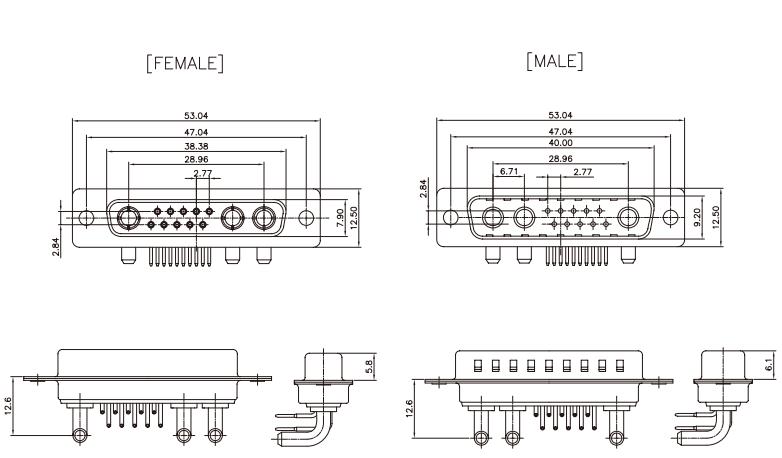
Models with the same contact layout share the mating-outline dimensions below. Values are in millimetres. Male and female mating widths differ, and their front views use opposite viewing directions.
| Layout and models | Overall flange length | Mounting centres | Female mating width | Male mating width | Power-contact centre span |
|---|---|---|---|---|---|
| 7W2: MP421A / MP422D / MP422M | 39.14 | 33.32 | 24.66 | 26.50 | 13.70 |
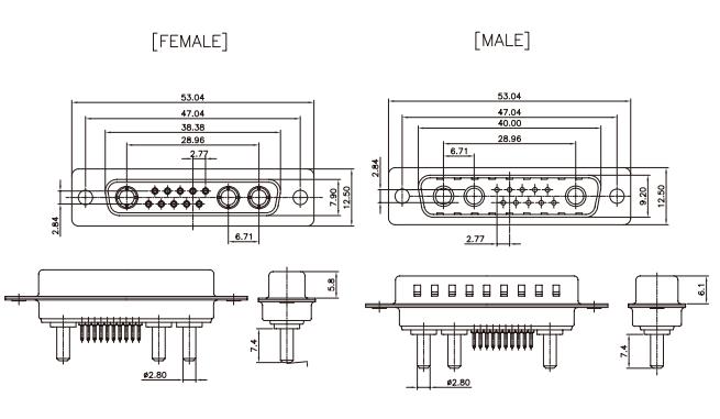
| 17W2: MP421B / MP422E / MP422N | 53.04 | 47.04 | 38.38 | 40.00 | 27.64 |
| 13W3: MP421C / MP422F / MP422O | 53.04 | 47.04 | 38.38 | 40.00 | 28.96 overall; 6.71 between the adjacent power contacts |
All layouts show a 12.50mm flange height, 7.90mm female mating-height reference, 9.20mm male mating-height reference, 2.77mm signal-contact pitch and 2.84mm signal-row spacing. The 7W2 signal layout also shows a 5.54mm longitudinal reference. Female and male mating projections are 5.8mm and 6.1mm respectively.
The solder-cup profiles show an 8.5mm termination projection and a Ø5.50mm outer reference. Use the selected type's ØA/ØB values for the power cups and the exact layout drawing for signal-contact positions.


MP422D, MP422E and MP422F use bent PCB terminations and show a 12.6mm flange-to-tail-centre reference. Their power-contact rating is 40A; their ordering fields specify gender, insulator colour, shell plating and contact plating.


MP422M, MP422N and MP422O use straight through-hole terminations, with Ø2.80mm power tails and a 7.4mm tail-length reference. Their power-contact rating is 40A. Select the exact gender and numbered contact layout before preparing the PCB footprint.