


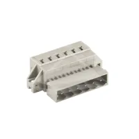


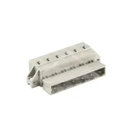

| Part Number: | ULO | - | TB440 | - | 8KRMB | - | 5.0 | - | 02 | P |
|---|---|---|---|---|---|---|---|---|---|---|
| Explanation: |
Brand |
Series Code TB410 - 2.5mm; 8KR only |
Counterplug Model 8KR - Plain; all seven pitches |
Pitch 2.5 - TB410 |
Poles 02–12 - TB410, 2.5mm |
Pole Suffix |
MCS 8KR counterplugs combine single-row spring cage wire termination with a shrouded pin interface. Wires enter the cage openings on the side opposite the mating interface, as shown in the outlines. These are wire-side connectors without PCB solder tails. Match the complete mating interface, pole count, keying and retention arrangement before selecting a counterpart.
| Pitch | Plain | Latch version | Retaining pegs | Pegs and latch | Mounting flanges | Flanges and latch | Poles |
|---|---|---|---|---|---|---|---|
| 2.5mm | TB410-8KR/2.5 | — | — | — | — | — | 2-12 |
| 3.5mm | TB420-8KR/3.5 | TB420-8KRMA/3.5 | 2-24 | ||||
| 3.81mm | TB430-8KR/3.81 | TB430-8KRMA/3.81 | |||||
| 5.0mm | TB440-8KR/5.0 | TB440-8KRB/5.0 | TB440-8KRC/5.0 | TB440-8KRD/5.0 | TB440-8KRMA/5.0 | TB440-8KRMB/5.0 | |
| 5.08mm | TB450-8KR/5.08 | — | TB450-8KRC/5.08 | — | TB450-8KRMA/5.08 | — | |
| 7.5mm | TB460-8KR/7.5 | TB460-8KRB/7.5 | TB460-8KRC/7.5 | TB460-8KRD/7.5 | TB460-8KRMA/7.5 | TB460-8KRMB/7.5 | |
| 7.62mm | TB470-8KR/7.62 | — | TB470-8KRC/7.62 | — | TB470-8KRMA/7.62 | — |
B and MB versions have the extended latch arrangement. C versions add retaining pegs; D combines the peg and latch arrangements. MA and MB add side mounting flanges. A dash identifies a configuration not listed in this series.
| Models | IEC overvoltage category / pollution degree | Current | Voltage | Impulse voltage |
|---|---|---|---|---|
| 8KR/2.5 | III / 2 | 4A | 250V | 2.5kV |
| 8KR and 8KRMA, 3.5mm and 3.81mm | 10A | |||
| 8KR/5.0 | III / 2 and III / 3 | 12A | 4kV | |
| 8KRB, 8KRC, 8KRD, 8KRMA and 8KRMB, 5.0mm | III / 3 | |||
| 8KR/5.08 | III / 2 | |||
| 8KRC and 8KRMA, 5.08mm | III / 3 | |||
| All 7.5mm and 7.62mm versions | 400V | 6kV |
| Pitch group | UL use group B current | UL use group B voltage | UL wire range | Solid wire | Flexible wire | Flexible wire with ferrule | Strip length |
|---|---|---|---|---|---|---|---|
| 2.5mm | 4A | 150V | 24-20AWG | 0.2-0.5mm² | 0.2-0.5mm² | 0.2-0.5mm² | 5-6mm |
| 3.5mm and 3.81mm | 10A | 300V | 24-16AWG | 0.2-1.5mm² | 0.2-1.5mm² | 0.2-1.5mm² | 7mm |
| 5.0mm, 5.08mm, 7.5mm and 7.62mm | 15A | 24-14AWG | 0.2-2.5mm² | 0.2-2.5mm² | 0.2-2.5mm² | 8-9mm |
UL use groups C and D have no specified ratings for these models. IEC and UL values apply under their respective stated conditions; the UL current does not replace the IEC current.
| Common property | Specification |
|---|---|
| Termination | Spring cage, single row |
| Housing material | PA66, insulation material group I, UL94V-0 |
| Contact pins | Tin-plated brass |
| Protection | IP20 |
| Operating temperature | -40°C to +105°C |
| Environmental compliance | RoHS |
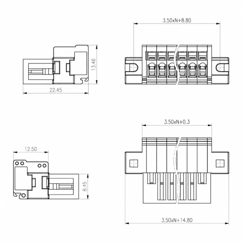
Dimensions below are in mm. P or N in a drawing denotes pole count. Contact span is pitch × (P-1). Length formulas describe the indicated feature along the pole row; mounting centres and overall flange width are different references.
| Model | Side-profile envelope | Length references along pole row |
|---|---|---|
| 8KR/2.5 | 20.30 × 11.80 | Overall row length 2.5(P+1) |
| 8KR/3.5 | 22.30 × 13.40 | Body 3.5P+1.40; mating opening 3.5P+0.30 |
| 8KRMA/3.5 | Body 3.5P+0.30; mounting centres 3.5P+8.80; overall flanges 3.5P+14.80 | |
| 8KR/3.81 | Body 3.81P+1.40 | |
| 8KRMA/3.81 | Mounting centres 3.81P+8.80; overall flanges 3.81P+14.80 |




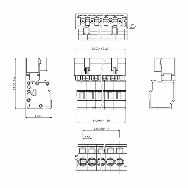
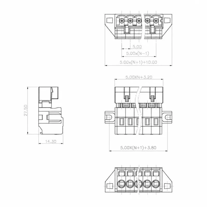
For the following formulas, s is the exact pitch: 5.0 or 5.08. Plain, B, C and D versions use a shroud length of sP+3.20 and a body length of sP+1.50. The plain version's interlock increases the indicated body extent to sP+2.00. MA versions use A=sP+3.20, D=A-0.20 and mounting-centre dimension E=D+5.80. These formulas apply only to configurations listed in the selection table.
| Model | Side-profile envelope | Mating-section width | Mounting detail |
|---|---|---|---|
| 8KR/5.0 and 8KR/5.08 | 27.50 × 14.50 | 8.50 | Plain housing |
| 8KRB/5.0 | 27.50 × 14.30 | 11.40 | Extended latch |
| 8KRC/5.0 | 27.50 × 14.50 | 8.50 | Peg projection 4.51; centre reference 12.15 |
| 8KRC/5.08 | Peg projection 4.50; centre reference 12.15 | ||
| 8KRD/5.0 | 11.50 | ||
| 8KRMA/5.0 and 8KRMA/5.08 | 8.50 | Slots 2.50; height reference 9.80 | |
| 8KRMB/5.0 | 11.50 | Slot centres 5(P+1)+3.80; slots 2.50; height reference 9.80 |





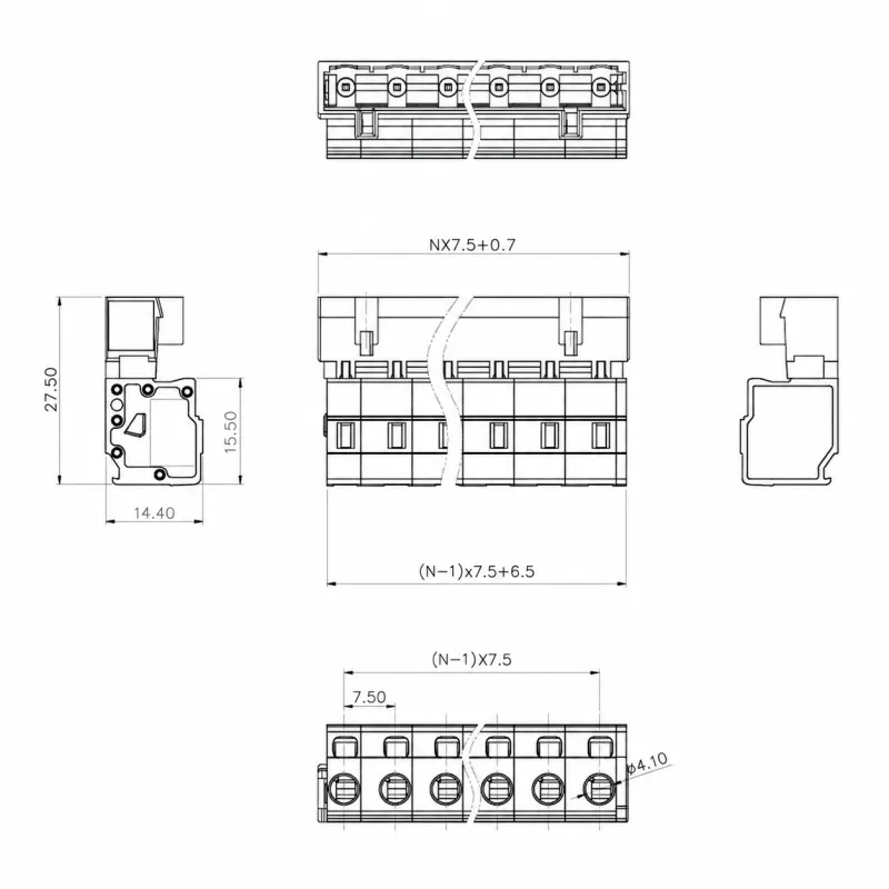
For the following formulas, s is 7.5 or 7.62. Plain, B, C and D versions have a shroud length of s(P-1)+8.20 and body length of s(P-1)+6.50; the indicated interlock extent is s(P-1)+7.00. MA flange versions use A=5+s(P-1)+3.20, D=A-0.20 and mounting-centre dimension E=D+5.80. MB/7.5 specifies a slot-centre distance of 7.5(P-1)+13.80.
| Model | Side-profile envelope | Mating-section width | Mounting detail |
|---|---|---|---|
| 8KR/7.5 and 8KR/7.62 | 27.50 × 14.50 | 8.40 | Plain housing |
| 8KRB/7.5 | 11.50 | Extended latch | |
| 8KRC/7.5 and 8KRC/7.62 | 8.40 | Peg projection 4.50; centre reference 12.15 | |
| 8KRD/7.5 | 11.50 | ||
| 8KRMA/7.5 and 8KRMA/7.62 | 8.50 | Slots 2.50; height reference 9.80 | |
| 8KRMB/7.5 | 11.50 |



Specify the complete model and pole count from the selection table. The model drawing uses XXP for pole count. Prepare conductors to the listed strip length and select the solid, flexible or ferruled conductor range as applicable. Use the exact model's mounting dimensions, retention geometry and contact arrangement to check the intended installation.
