



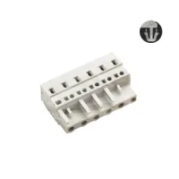
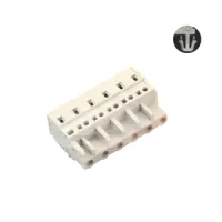


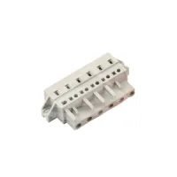


| Part Number: | ULO | - | TB440 | - | 8KMB | - | 5.0 | - | 02 | P |
|---|---|---|---|---|---|---|---|---|---|---|
| Explanation: |
Brand |
Series Code TB410 - 2.5mm; 8K or 8KG |
Plug Model 8K - Plain; all seven pitches |
Pitch 2.5 - TB410 |
Poles 02–12 - TB410, 2.5mm |
Pole Suffix |
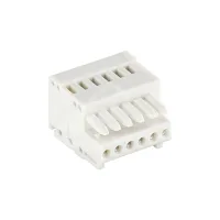
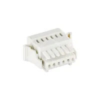
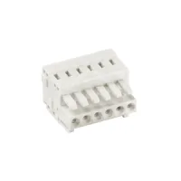
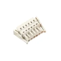
MCS 8K wire-side plugs provide single-row spring cage connections in seven pitches. Plain bodies, rear retaining pegs, paired end levers and mounting flanges have different clearance requirements. Select the full model and pole count, then match the mating geometry and retention features to the intended counterpart.
| Pitch | Available models | Pole count |
|---|---|---|
| 2.5mm | TB410-8K/2.5; TB410-8KG/2.5 | 2-12 |
| 3.5mm | TB420-8K/3.5; TB420-8KG/3.5 | 2-24 |
| 3.81mm | TB430-8K/3.81; TB430-8KG/3.81 | |
| 5.0mm | TB440-8K/5.0; TB440-8KB/5.0; TB440-8KC/5.0; TB440-8KD/5.0; TB440-8KG/5.0; TB440-8KGB/5.0; TB440-8KMA/5.0; TB440-8KMB/5.0 | |
| 5.08mm | TB450-8K/5.08; TB450-8KC/5.08; TB450-8KG/5.08; TB450-8KMA/5.08 | |
| 7.5mm | TB460-8K/7.5; TB460-8KB/7.5; TB460-8KC/7.5; TB460-8KD/7.5; TB460-8KG/7.5; TB460-8KGB/7.5; TB460-8KMA/7.5; TB460-8KMB/7.5 | |
| 7.62mm | TB470-8K/7.62; TB470-8KC/7.62; TB470-8KG/7.62; TB470-8KMA/7.62 |
| Variant | Retention arrangement | Selection detail |
|---|---|---|
| 8K, 8KB | Plain body | 8KB has an alternative actuator profile where listed. |
| 8KC, 8KD | Rear retaining pegs | 8KD has an alternative actuator profile where listed. |
| 8KG, 8KGB | Paired end levers | 8KGB has an alternative actuator profile where listed. |
| 8KMA, 8KMB | End mounting flanges | A and B actuator arrangements have separate outlines; compare the exact flange dimensions. |
IEC values apply under the conditions in the table. The two 2.5mm models have different IEC ratings. UL use-group values are listed separately and should not be substituted for IEC values.
| Models | IEC current | IEC voltage | Impulse voltage | Overvoltage category | Pollution degree |
|---|---|---|---|---|---|
| TB410-8K/2.5 | 6A | 100V | 2.5kV | III | 2 |
| TB410-8KG/2.5 | 4A | 250V | |||
| All listed 3.5mm and 3.81mm models | 10A | ||||
| All listed 5.0mm and 5.08mm models | 16A | 4kV | 3 | ||
| All listed 7.5mm and 7.62mm models | 400V | 6kV |
| Models by pitch | UL use group | Current | Voltage |
|---|---|---|---|
| 2.5mm | B | 4A | 150V |
| 3.5mm, 3.81mm | 10A | 300V | |
| 5.0mm, 5.08mm, 7.5mm, 7.62mm | 15A | ||
| All models | C and D | Not specified | Not specified |
| Pitch group | Solid conductor | Flexible conductor | Ferruled conductor | UL wire range | Strip length |
|---|---|---|---|---|---|
| 2.5mm | 0.2-0.5mm² | 0.2-0.5mm² | 0.2-0.5mm² | 24-20AWG | 5-6mm |
| 3.5mm, 3.81mm | 0.2-1.5mm² | 0.2-1.5mm² | 0.2-1.5mm² | 24-16AWG | 7mm |
| 5.0mm, 5.08mm, 7.5mm, 7.62mm | 0.2-2.5mm² | 0.2-2.5mm² | 0.2-2.5mm² | 24-14AWG | 8-9mm |
| Property | All models |
|---|---|
| Termination | Spring cage |
| Rows | 1 |
| Protection rating | IP20 |
| Operating temperature | -40°C to +105°C |
| Insulation | PA66, material group I |
| Flammability classification | UL94V-0 |
| Contact material and finish | Tin-plated brass |
| RoHS compliance | Specified |
P, N and XX denote pole count in the respective drawings. All length expressions below are in millimetres. Keep body width, contact span and the complete width including retention features separate when calculating clearances.
| Model | Side-view dimensions | Row dimensions |
|---|---|---|
| TB410-8K/2.5 | 11.8 × 17.1mm; main body depth 11.4mm | Body 2.5P + 1.5; complete width including 0.6mm protrusion 2.5P + 2.1 |
| TB410-8KG/2.5 | 11.8 × 17.1mm; mating projection 5.7mm | Module row 2.5P; contact span 2.5(P−1); width across end levers 2.5P + 11.8 |


| Model | Side-view dimensions | Row width |
|---|---|---|
| TB420-8K/3.5 | 13.5 × 18.7mm | Module row 3.5P, plus 1.4mm endplate |
| TB420-8KG/3.5 | 13.4 × 18.6mm | Across end levers 3.5P + 11.8 |
| TB430-8K/3.81 | 13.5 × 18.7mm | Module row 3.81P, plus 1.4mm endplate |
| TB430-8KG/3.81 | 13.4 × 18.6mm | Across end levers 3.81P + 11.8 |
Contact span is pitch × (P−1). The lever versions have a 6.6mm mating projection. The 3.81mm lever outline below depicts the configuration for three or more poles; the model range includes 2-24 poles.


TB440-8K, 8KB, 8KC and 8KD at 5.0mm pitch have a nominal 14.5 × 26.4mm side-view envelope and body width 5P + 1.5. The C/D retaining pegs project 4.5mm and have a centre height of 12.15mm in the detailed drawing. Match the actuator profile and retention arrangement to the selected variant.


| Models | Side-view dimensions | Overall width | Retention detail |
|---|---|---|---|
| TB440-8KG/5.0, TB440-8KGB/5.0 | 14.5 × 30mm | 5P + 16.5 | End extensions 8.5mm and 8.0mm beyond the 5P module row |
| TB440-8KMA/5.0, TB440-8KMB/5.0 | 14.5 × 26.4mm | 5P + 14.8 | Mounting-slot centre distance 5P + 8.8; slot width 2.5mm; centre height 9.8mm |


| Model | Side-view dimensions | Overall row width |
|---|---|---|
| TB450-8K/5.08 | 14.5 × 26.4mm | 5.08P + 1.5 |
| TB450-8KC/5.08 | 5.08P + 1.5, with rear retaining pegs | |
| TB450-8KG/5.08 | 14.3 × 30mm | 5.08P + 16.5 across end levers |
| TB450-8KMA/5.08 | 14.5 × 26.4mm | 5.08P + 14.8 across flanges |
The flange mounting-slot centre distance is 5.08P + 8.8, with 2.5mm slot width and 9.8mm centre height. The KC retaining pegs project 4.5mm at a 12.15mm centre height. For shared pitch drawings, use the 5.08mm annotations.


TB460-8K, 8KB, 8KC and 8KD at 7.5mm pitch have a nominal 14.5 × 26.4mm side-view envelope. The last module is 5mm wide, giving an inner row of 7.5(P−1) + 5.0 and a body width of 7.5(P−1) + 6.5. C/D retaining pegs project 4.5mm at a centre height of 12.15mm.


| Models | Side-view dimensions | Overall width | Mounting-slot centre distance |
|---|---|---|---|
| TB460-8KG/7.5, TB460-8KGB/7.5 | 14.5 × 30mm | 7.5(P−1) + 21.5 | Not applicable; paired end levers |
| TB460-8KMA/7.5 | 14.5 × 26.4mm | 7.5(P−1) + 19.4 | 7.5(P−1) + 13.8 |
| TB460-8KMB/7.5 | 7.5(P−1) + 19.8 |
Lever versions add 8.5mm and 8.0mm outside the 7.5(P−1) + 5.0 module row. Flange versions use 2.5mm slots at a 9.8mm centre height. The MA and MB overall widths differ; retain their respective dimensions when allocating space.


| Model | Side-view dimensions | Overall row width |
|---|---|---|
| TB470-8K/7.62 | 14.5 × 26.4mm | 7.62(P−1) + 6.5 |
| TB470-8KC/7.62 | 7.62(P−1) + 6.5, with rear retaining pegs | |
| TB470-8KG/7.62 | 14.5 × 30mm | 7.62(P−1) + 21.5 across end levers |
| TB470-8KMA/7.62 | 14.5 × 26.4mm | 7.62(P−1) + 19.4 across flanges |
The 7.62mm module row ends with a 5mm module. The KC peg projection is 4.5mm with 12.15mm centre height. The KMA mounting-slot centres are 7.62(P−1) + 13.8 apart, with 2.5mm slot width and 9.8mm centre height.


Apply individual tolerances where stated. Otherwise, the following general dimension and geometric tolerances apply. Dimension ranges and deviations in the first table are in millimetres.
| Dimension range | Total pitch tolerance | Nominal dimension tolerance |
|---|---|---|
| Over 0 to 30 | ±0.18 | ±0.20 |
| Over 30 to 53 | ±0.20 | ±0.25 |
| Over 53 to 70 | ±0.25 | ±0.30 |
| Over 70 to 90 | ±0.30 | ±0.35 |
| Over 90 to 115 | ±0.35 | ±0.44 |
| Over 115 to 150 | ±0.44 | ±0.55 |
| Over 150 to 200 | ±0.55 | ±0.70 |
| Over 200 to 250 | ±0.70 | ±0.80 |
| Over 250 to 320 | ±0.75 | ±0.90 |
| Geometric characteristic | Applicable range | Tolerance |
|---|---|---|
| Perpendicularity | Over 0 to 10mm | 0.2mm |
| Over 10mm | 0.3mm | |
| Symmetry | All | 0.3mm |
| Straightness and parallelism | Over 0 to 100mm | 0.2mm |
| Over 100 to 150mm | 0.3mm | |
| Over 150mm | 0.5mm |
Specify the full TB model, pitch, retention variant and pole count. XXP identifies the selected pole count in the model drawings. Allow access to the spring cage actuators and wire entry, and include the complete lever or flange envelope in the installation layout. Check the exact model attachment for its contact arrangement and mounting detail.
