


| Part Number: | ULO | - | TB440 | - | 8C | - | 5.0 | - | 02 | P |
|---|---|---|---|---|---|---|---|---|---|---|
| Explanation: |
Brand |
Series Code TB440 - 5.0mm; 8A, 8B, 8C or 8D |
PCB Terminal Model 8A - A actuator layout, side solder tails; all four pitches |
Pitch 5.0 - TB440 |
Poles 02–24 - Two-digit count from 2 to 24 poles |
Pole Suffix |
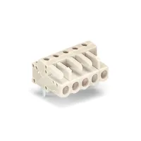
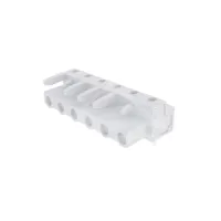
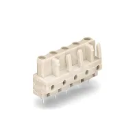
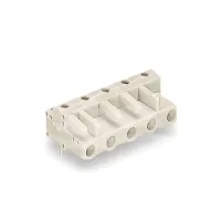
MCS 8A/B/C/D terminal blocks provide single-row spring cage wire connections and solder tails for PCB mounting. A and C layouts position the tails on the side of the housing; B and D layouts position them beneath the housing in the upright reference views. C and D use a different actuator profile from A and B. Select the complete model, pitch and pole count, then check its outline and tail positions against the board layout.
| Model | Pitch | Poles | Actuator layout | Tail position in upright reference view |
|---|---|---|---|---|
| TB440-8A/5.0 | 5.0mm | 2-24 | A | Side |
| TB440-8B/5.0 | B | Bottom | ||
| TB440-8C/5.0 | C | Side | ||
| TB440-8D/5.0 | D | Bottom | ||
| TB450-8A/5.08 | 5.08mm | A | Side | |
| TB450-8B/5.08 | B | Bottom | ||
| TB460-8A/7.5 | 7.5mm | A | Side | |
| TB460-8B/7.5 | B | Bottom | ||
| TB460-8C/7.5 | C | Side | ||
| TB460-8D/7.5 | D | Bottom | ||
| TB470-8A/7.62 | 7.62mm | A | Side | |
| TB470-8B/7.62 | B | Bottom |
The IEC values below apply at overvoltage category III and pollution degree 3. The separate UL use-group ratings should be selected for the applicable use group.
| Models | IEC current | IEC voltage | Rated impulse voltage | Overvoltage category | Pollution degree |
|---|---|---|---|---|---|
| TB440-8A, 8B, 8C, 8D /5.0 | 12A | 250V | 4kV | III | 3 |
| TB450-8A, 8B /5.08 | |||||
| TB460-8A, 8B, 8C, 8D /7.5 | 400V | 6kV | |||
| TB470-8A, 8B /7.62 |
| Applicable models | UL use group | Current | Voltage |
|---|---|---|---|
| All 12 models | B | 10A | 300V |
| C | Not specified | Not specified | |
| D |
| Property | All models |
|---|---|
| Wire termination | Spring cage |
| Rows | 1 |
| Stripping length | 6-7mm |
| Wire cross-section and AWG range | Not specified |
| Protection rating | IP20 |
| Operating temperature | -40°C to +105°C |
| Insulation material | PA66 |
| Insulation material group | I |
| Flammability classification | UL94V-0 |
| Contact material and finish | Tin-plated brass |
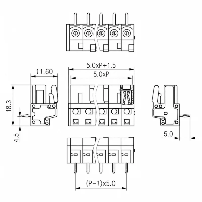
P is the pole count. All dimensions and length expressions in this section are in millimetres. The housing section is 11.6 × 18.3; row length is L = 5P + 1.5. A/C tails project from the side, while B/D tails project from the bottom. A/C drawings show a 5mm tail projection and a tail centre 4.5mm from the lower housing edge. D has a 5mm projection beneath the mounting plane and a 4mm pin offset in the side view.
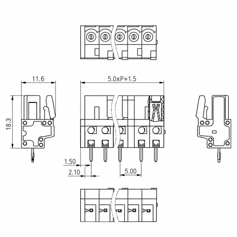


For TB450-8A/5.08 and TB450-8B/5.08, use the 5.08mm pitch values shown in parentheses in the drawings. The housing section is 11.6 × 18.3mm and length is L = 5.08P + 1.5. The A layout shows a 5mm side-tail projection and 4.5mm height from the lower housing edge.


| Models | Housing section | Overall row length L | Tail projection |
|---|---|---|---|
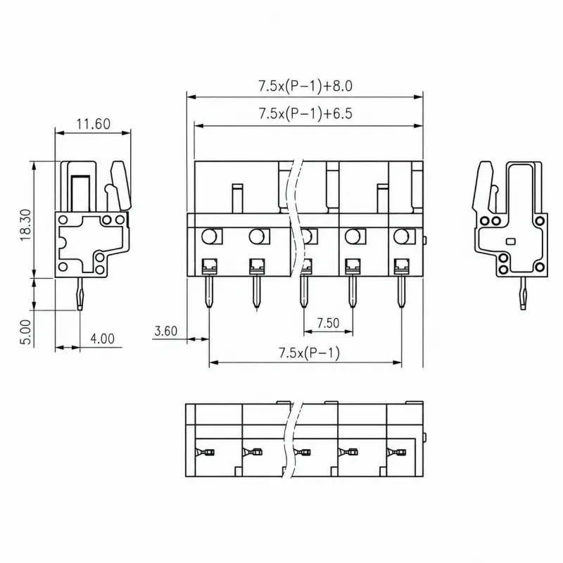
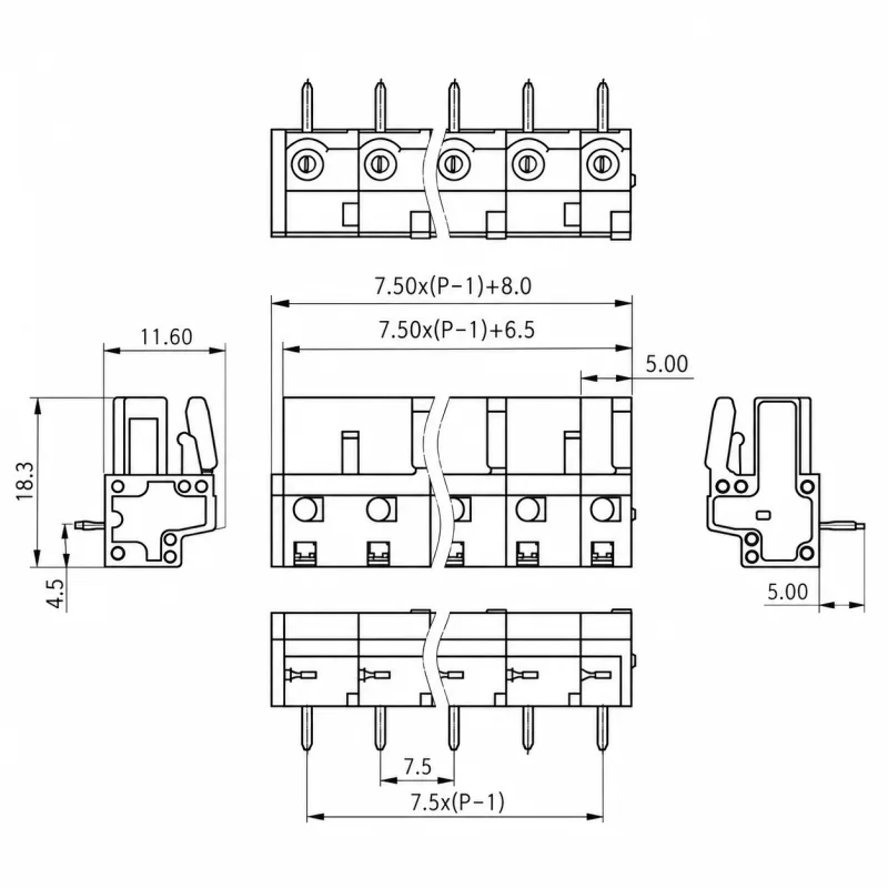
| TB460-8A/7.5, TB460-8B/7.5 | 11.6 × 18.3mm | 7.5(P−1) + 8.0mm | 5mm |
| TB460-8C/7.5, TB460-8D/7.5 | 7.5(P−1) + 6.5mm |
The A/B drawings also show an inner row length of 7.5(P−1) + 6.5. For B, the first-pin offset from the outside end is 3.60mm and the side-view pin offset is 4mm. C/D have a different overall end allowance; retain the model-specific outline when setting board clearances.


For TB470-8A/7.62 and TB470-8B/7.62, XX in the drawings is the pole count. Select the 7.62mm annotations from the shared pitch drawings. The housing section is 11.6 × 18.4mm, overall row length is 7.62XX − 1.04 and pin span is 7.62(XX−1). Both have a 5mm tail projection. The A side view shows a 4.45mm pin offset; B shows a 4mm offset.


The following general tolerances apply unless an individual dimension states otherwise. Range limits and deviations are in millimetres.
| Dimension range | Total pitch tolerance | Nominal dimension tolerance |
|---|---|---|
| Over 0 to 30 | ±0.18 | ±0.20 |
| Over 30 to 53 | ±0.20 | ±0.25 |
| Over 53 to 70 | ±0.25 | ±0.30 |
| Over 70 to 90 | ±0.30 | ±0.35 |
| Over 90 to 115 | ±0.35 | ±0.44 |
| Over 115 to 150 | ±0.44 | ±0.55 |
| Over 150 to 200 | ±0.55 | ±0.70 |
| Over 200 to 250 | ±0.70 | ±0.80 |
| Over 250 to 320 | ±0.75 | ±0.90 |
| Geometric characteristic | Applicable dimension range | Tolerance |
|---|---|---|
| Perpendicularity | Over 0 to 10mm | 0.2mm |
| Over 10mm | 0.3mm | |
| Symmetry | All | 0.3mm |
| Straightness and parallelism | Over 0 to 100mm | 0.2mm |
| Over 100 to 150mm | 0.3mm | |
| Over 150mm | 0.5mm |
Specify the complete TB440, TB450, TB460 or TB470 model, its A/B/C/D layout, pitch and pole count. XXP in the model drawing denotes the selected 02-24 pole count. Keep wire-entry access, actuator clearance and the actual solder-tail arrangement in the board design; a shared pitch does not make different layouts interchangeable.
