| Part Number: | MDB | L | 32 | TF | - | 50 | J | - | Z73 | S |
|---|---|---|---|---|---|---|---|---|---|---|
| Explanation: |
Series and Magnet MB - MB cylinder without a built-in magnet; omit magnetic-switch fields |
Mounting B - Basic mounting |
Bore 32 - 32mm |
Port Thread Blank - Rc thread; omit the thread suffix |
Stroke 50 - 50mm stroke |
Cover and Cushion Option Blank - No protective cover; pneumatic cushioning at both ends |
Magnetic Switch Blank - No switch; omit the switch code, preceding hyphen and quantity code |
Switch Quantity Blank - Two switches; omit the quantity suffix |
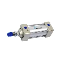
MB cylinders provide double-acting pneumatic motion in 32–125mm bores. Choose the bore and stroke, mounting arrangement, port thread, cushioning and magnetic sensing options as a complete configuration. The pictured MBB50X75 is a basic-mount cylinder with 50mm bore and 75mm stroke.
| Ordering field | Code | Meaning |
|---|---|---|
| Magnet | Blank / D | Without / with built-in magnet |
| Mounting | B | Basic type |
| Mounting | L | Axial foot mounting |
| Mounting | F / G | Rod-side flange / rear flange |
| Mounting | C / D | Single ear / double ear |
| Mounting | T | Ear mounting type |
| Bore | 32, 40, 50, 63, 80, 100, 125 | Bore in millimeters |
| Port thread | Blank / TN / TF | Rc / NPT / G |
| Stroke | 50 | Example: 50mm |
| Protective cover | Blank / J / K | None / nylon canvas / heat-resistant canvas |
| Cushioning | Blank / N | Air cushioning at both ends / rubber cushioning |
| Magnetic switch | Blank or selected switch code | No switch or selected model; requires a built-in magnet |
| Switch quantity | Blank / S / n | Two / one / specified quantity |
The example MDBL32□-50□-Z73□ identifies a magnetic cylinder, L mounting, 32mm bore, 50mm stroke and Z73 switch; the square placeholders represent option positions. Protective canvas options do not establish a higher cylinder operating temperature.
| Parameter | 32mm | 40mm | 50mm | 63mm | 80mm | 100mm | 125mm |
|---|---|---|---|---|---|---|---|
| Medium | Air | ||||||
| Action | Double acting | ||||||
| Operating pressure | 0.05–1.0MPa | ||||||
| Temperature without magnetic switch | -10–70°C | ||||||
| Temperature with magnetic switch | -10–60°C | ||||||
| Operating speed | 50–1000mm/s | 50–700mm/s | |||||
| Standard cushioning | Air cushioning at both ends | ||||||
| Lubrication | Not required | ||||||
| Rc port size | 1/8 | 1/4 | 1/4 | 3/8 | 3/8 | 1/2 | 1/2 |
If lubrication is used, the specified oil is ISO VG32 turbine oil. Match the selected thread option to the connected fittings.
The N rubber-cushion configuration increases total cylinder length relative to the air-cushion version.
| Bore | Additional total length |
|---|---|
| 32mm, 40mm | 6mm |
| 50mm, 63mm | 8mm |
| 80mm, 100mm | 10mm |
| 125mm | 12mm |
| Bore (mm) | Standard strokes (mm) | Switch models | Switch mounting part |
|---|---|---|---|
| 32, 40 | 25, 50, 75, 100, 125, 150, 175, 200, 250, 300, 350, 400, 450, 500 | Z73, Z76, Y59A, Y59B, Y7NW, Y7BA | BMB4-032 |
| 50, 63 | 25, 50, 75, 100, 125, 150, 175, 200, 250, 300, 350, 400, 450, 500, 600 | BMB4-050 | |
| 80, 100 | 25, 50, 75, 100, 125, 150, 175, 200, 250, 300, 350, 400, 450, 500, 600, 700, 800 | BA4-060 | |
| 125 | 25, 50, 75, 100, 125, 150, 175, 200, 250, 300, 350, 400, 450, 500, 600, 700, 800 | BA4-080 |
Nonstandard strokes are available as configuration selections. Select the switch model, quantity and mounting hardware separately from the cylinder stroke.
The tolerance bands below describe finished stroke tolerance; they do not expand the standard-stroke choices above.
| Nominal stroke | Lower deviation | Upper deviation |
|---|---|---|
| Up to 250mm | 0mm | +1.0mm |
| 251–1000mm | 0mm | +1.4mm |
| 1001–1500mm | 0mm | +1.8mm |
