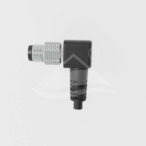
These black sensor and actuator cable assemblies have an M8 connector at one end and a free cable end for termination. The connector uses an M8×1.0 mating thread and soldered internal wire connections. Select the connector gender and exit direction before specifying the contact arrangement and cable options.
Model family
Connector contacts
Cable exit
ULO-CC02-M8X-XXP-MM-PMXX-SLXXX
Male
Straight
ULO-CC02-M8X-XXP-FF-PMXX-SLXXX
Female
Straight
ULO-CC02-M8X-XXP-MM-PMXX-SRXXX
Male
Angled
ULO-CC02-M8X-XXP-FF-PMXX-SRXXX
Female
Angled
Coding and electrical ratings
Coding
Contacts
Rated current
Rated voltage
Withstand voltage
A
3 or 4
3A
60VDC
850V
B
5
3A
30V
650V
A
6 or 8
1.5A
30V
650V
Withstand waveform and test duration are not specified. Coding and contact count must match the mating connector; the available combinations are those listed above.
Contact numbers and wire colours
The wire-colour assignments below apply to the four model families. Use the male or female contact-face drawing in the matching PDF to locate the numbered contacts.
Contact number
A coding, 3 contacts
A coding, 4 contacts
B coding, 5 contacts
A coding, 6 contacts
A coding, 8 contacts
1
Brown
Brown
Brown
Brown
White
2
Not fitted
White
White
White
Brown
3
Blue
Blue
Blue
Blue
Green
4
Black
Black
Black
Black
Yellow
5
Not fitted
Not fitted
Grey
Grey
Grey
6
Not fitted
Not fitted
Not fitted
Pink
Pink
7
Not fitted
Not fitted
Not fitted
Not fitted
Blue
8
Not fitted
Not fitted
Not fitted
Not fitted
Red
Cable jacket, shielding and length
Selection
Code
Option
Cable jacket
A
PVC, UL2517 wire style
Cable jacket
B
PUR, UL20549 wire style
Shielding
SH
Shielded cable
Shielding
No SH designation
Unshielded cable
Cable length
01 through 99
1-99m selection range
Nominal cable length
Length tolerance
1-5m
±50mm
6-10m
±100mm
11-30m
±200mm
31-99m
±500mm
The length, jacket and shielding options are listed for each of these four families. The family identifiers contain placeholders; specify the required options using the individual model legend.
Materials and service conditions
Characteristic
Specification
Contact resistance
≤3mΩ
Protection rating
IP67
Operating temperature
-40°C to +85°C
Mating life
≥100 insertion and withdrawal cycles
Contact material
CuZn copper-zinc alloy
Contact surface
Gold
Contact carrier
PU polyurethane
Moulded body
TPU thermoplastic polyurethane
Metal coupling ring
Nickel-plated copper alloy
Sealing material
Silicone
Flammability classification
UL94V-0
Compliance
RoHS
Straight connector dimensions
Model configuration
Reference body length
Mating thread
Male, MM-PMXX-SLXXX
37.3mm
M8×1.0
Female, FF-PMXX-SLXXX
37.3mm
M8×1.0
MM-PMXX-SLXXX male connector with 37.3mm reference body length and separately indicated cable length L.FF-PMXX-SLXXX female connector with 37.3mm reference body length and separately indicated cable length L.
Angled connector dimensions
Model configuration
Reference dimensions
Mating thread
Male, MM-PMXX-SRXXX
27mm × 26mm
M8×1.0
Female, FF-PMXX-SRXXX
21mm × 26mm
M8×1.0
MM-PMXX-SRXXX angled male connector with 27mm × 26mm reference dimensions.FF-PMXX-SRXXX angled female connector with 21mm × 26mm reference dimensions.
General drawing tolerance
Value
One decimal place, .X
±0.3mm
Two decimal places, .XX
±0.1mm
Angles
±1°
Reference body dimensions and cable-length tolerances are separate. Consult the matching PDF for the full outline and connector-face orientation.