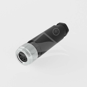
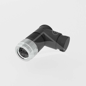
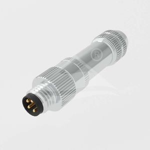
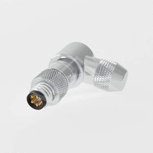
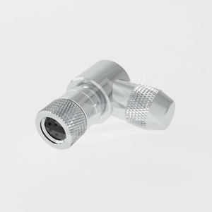
Eight field-wireable connector families cover male and female contacts, straight and angled cable exits, and shielded or unshielded construction. Each uses an M8×1.0 mating thread. Choose the coding and contact arrangement to match the mating device.
Model family
Contacts
Body
Shielding
ULO-CC02-M8X-XXP-MM-PX-SL001
Male
Straight
Unshielded
ULO-CC02-M8X-XXP-FF-PX-SL001
Female
Straight
Unshielded
ULO-CC02-M8X-XXP-MM-PX-SR001
Male
Angled
Unshielded
ULO-CC02-M8X-XXP-FF-PX-SR001
Female
Angled
Unshielded
ULO-CC02-M8X-XXP-MM-PXSH-SL001
Male
Straight
Shielded
ULO-CC02-M8X-XXP-FF-PXSH-SL001
Female
Straight
Shielded
ULO-CC02-M8X-XXP-MM-PXSH-SR001
Male
Angled
Shielded
ULO-CC02-M8X-XXP-FF-PXSH-SR001
Female
Angled
Shielded
Contact arrangements and ratings
Coding
Contact count
Rated current
Rated voltage
Withstand voltage
A
3 or 4
3A
60VDC
850V
B
5
3A
30V
650V
A
6 or 8
1.5A
30V
650V
Withstand waveform and test duration are not specified. The five-contact drawing uses B coding; the three-, four-, six- and eight-contact drawings use A coding. Match the individual face drawing and contact numbers rather than selecting by thread size alone.
Field termination options
Option code
Termination
A
Field assembly with solder termination
S
Plastic-nut field assembly with solder termination
B
Field assembly with screw termination
W
Plastic-nut field assembly with screw termination
The family codes include placeholders for coding, contact count and termination. Use the selected model's PDF to specify the required configuration.
Materials and operating conditions
Characteristic
Specification
Contact resistance
≤3mΩ
Protection rating
IP67
Operating temperature
-40°C to +85°C
Mating life
≥100 insertion and withdrawal cycles
Contact material
CuZn copper-zinc alloy
Contact surface
Gold
Contact carrier
PA polyamide
Seal
Silicone
Metal ring, shielded versions
Nickel-plated copper alloy
Flammability classification
UL94V-0
Compliance
RoHS
Unshielded body dimensions
Configuration
Reference dimensions
Other drawing dimensions
Straight male, MM-PX-SL001
49mm length
Ø12mm; SW11
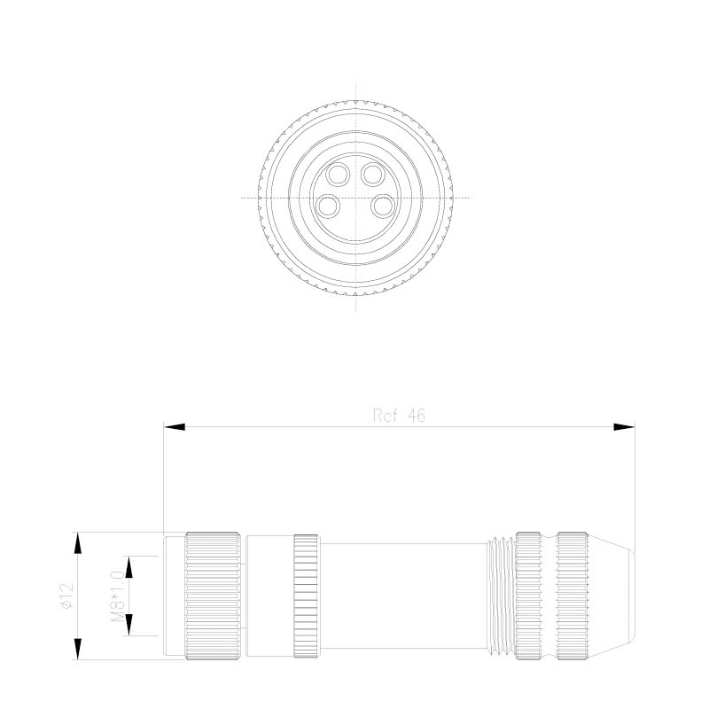
Straight female, FF-PX-SL001
44mm length
Ø12mm; SW11
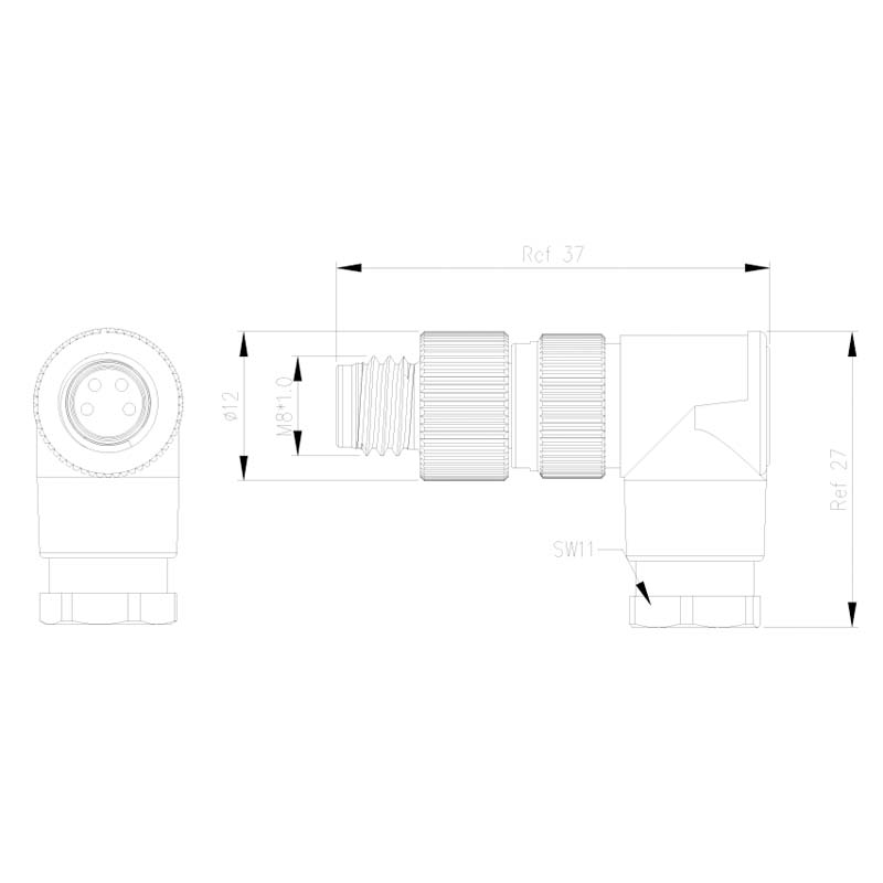
Angled male, MM-PX-SR001
37mm × 27mm
Ø12mm; SW11
Angled female, FF-PX-SR001
31mm × 24mm
Ø12mm; SW11
MM-PX-SL001 straight male body with 49mm reference length.FF-PX-SL001 straight female body with 44mm reference length.MM-PX-SR001 angled male body with 37mm × 27mm reference dimensions.FF-PX-SR001 angled female body with 31mm × 24mm reference dimensions.
30mm reference length and height; 23mm reference centreline-to-cable-entry distance; Ø12mm
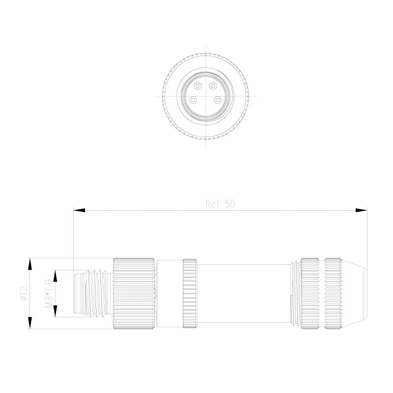
MM-PXSH-SL001 shielded straight male body with 50mm reference length.FF-PXSH-SL001 shielded straight female body with 46mm reference length.MM-PXSH-SR001 shielded angled male body with 38.45mm length.FF-PXSH-SR001 shielded angled female body with 30mm reference length and height.
General drawing tolerance
Value
One decimal place, .X
±0.3mm
Two decimal places, .XX
±0.1mm
Angles
±1°
Reference dimensions retain their reference designation. The corresponding PDFs include the contact-face drawings and model option legends.