
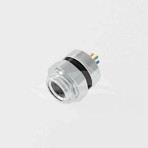

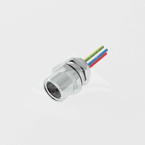

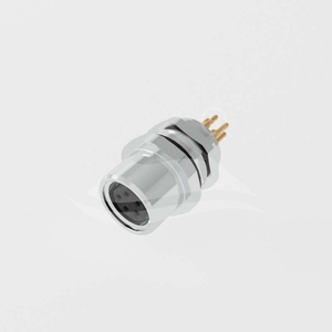
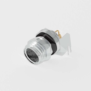
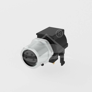

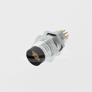
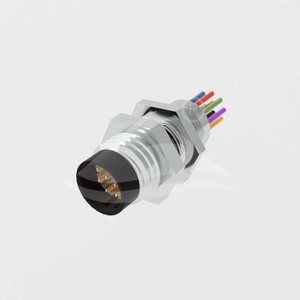
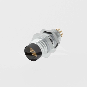

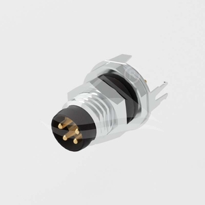
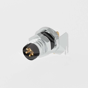

These device receptacles provide an M8×1.0 mating interface with A-coded 3, 4, 6 or 8 contacts, or B-coded 5 contacts. Select the mating gender, panel mounting arrangement and internal termination together. Solder cups, individual wire leads, straight PCB pins and right-angle PCB pins have different installation requirements.
| Model family | Panel mounting | Mounting thread shown | Termination | Shielding designation | Mating cycles |
|---|---|---|---|---|---|
| ULO-CC02-M8X-XXP-FF-SD-SF001 | Rear | M10×0.75 | Solder cups | Not specified | >50 |
| ULO-CC02-M8X-XXP-FF-SD-SFAXX | Rear | M10×0.75 | Individual wire leads | Not specified | >50 |
| ULO-CC02-M8X-XXP-FF-SD-SH003 | Front | M8×1.0 | Solder cups | Not specified | >50 |
| ULO-CC02-M8X-XXP-FF-SD-SHCXX | Front | M8×1.0 | Individual wire leads | Not specified | >50 |
| ULO-CC02-M8X-XXP-FF-SP-SF001 | Rear | M10×0.75 | 180° straight PCB pins | Unshielded | >50 |
| ULO-CC02-M8X-XXP-FF-SPSH-SF001 | Rear | M10×0.75 | 180° straight PCB pins | Shielded | ≥100 |
| ULO-CC02-M8X-XXP-FF-SP-SH003 | Front | M8×1.0 | 180° straight PCB pins | Unshielded | >50 |
| ULO-CC02-M8X-XXP-FF-SRSH-SF001 | Rear | M10×0.75 | 90° PCB pins | Shielded | ≥100 |
| ULO-CC02-M8X-XXP-FF-SR-SF005 | Rear | M8×1.0, plastic configuration | 90° PCB pins | Unshielded | ≥100 |
| Model family | Panel mounting | Mounting thread shown | Termination | Shielding designation | Mating cycles |
|---|---|---|---|---|---|
| ULO-CC02-M8X-XXP-MM-SD-SF003 | Rear | M8×1.0 | Solder cups | Not specified | >50 |
| ULO-CC02-M8X-XXP-MM-SD-SFCXX | Rear | M8×1.0 | Individual wire leads | Not specified | >50 |
| ULO-CC02-M8X-XXP-MM-SD-SH002 | Front | M8×0.5 | Solder cups | Not specified | >50 |
| ULO-CC02-M8X-XXP-MM-SD-SHBXX | Front | M8×0.5 | Individual wire leads | Not specified | >50 |
| ULO-CC02-M8X-XXP-MM-SP-SH002 | Front | M8×0.5 | 180° straight PCB pins | Unshielded | >50 |
| ULO-CC02-M8X-XXP-MM-SP-SF003 | Rear | M8×1.0 | 180° straight PCB pins | Unshielded | >50 |
| ULO-CC02-M8X-XXP-MM-SPSH-SF003 | Rear | M8×1.0 | 180° straight PCB pins | Shielded | ≥100 |
| ULO-CC02-M8X-XXP-MM-SRSH-SF003 | Rear | M8×1.0 | 90° PCB pins | Shielded | ≥100 |
| ULO-CC02-M8X-XXP-MM-SR-SF005 | Rear | M8×1.0, plastic configuration | 90° PCB pins | Unshielded | ≥100 |
| Coding | Contacts | Rated current | Rated voltage | Withstand voltage |
|---|---|---|---|---|
| A | 3 or 4 | 3A | 60VDC | 850V |
| B | 5 | 3A | 30VDC | 650V |
| A | 6 or 8 | 1.5A | 30VDC | 650V |
Withstand waveform and test duration are unspecified. Three-contact arrangements use positions 1, 3 and 4. The corresponding male and female face drawings show the orientation of each contact; coding and contact count must both match the mating connector.
| Characteristic | Specification |
|---|---|
| Contact resistance | ≤3mΩ |
| Protection rating | IP67 |
| Operating temperature | -40°C to +85°C |
| Contacts and finish | CuZn copper-zinc alloy with gold contact surface |
| Contact carrier | PA polyamide |
| Metal ring material | Nickel-plated copper alloy |
| Seal | Silicone |
| Flammability classification | UL94V-0 |
| Compliance | RoHS |
The X and XX positions are placeholders. The contact-count codes are 03, 04, 05, 06 and 08; the coding position is A or B according to the supported contact arrangement. Mounting legends distinguish the thread codes below. These legends do not establish every possible combination of mounting, termination and shielding; the outlines apply to the specific configurations identified above.
| Mounting thread | Numeric suffix code | Wire-lead mounting code |
|---|---|---|
| M10×0.75 | 001 | A |
| M8×0.5 | 002 | B |
| M8×1.0 | 003 | C |
| M12×1.0 | 004 | D |
| M8×1.0, plastic configuration | 005 | Not listed |
The following length codes are listed for FF-SD-SFAXX, FF-SD-SHCXX, MM-SD-SFCXX and MM-SD-SHBXX. L is measured from the rear body face to the lead end. Jacket material, conductor cross section and wire-colour assignments are unspecified for these individual-lead receptacles.
| Lead-length code | Length L |
|---|---|
| 15 | 150mm |
| 30 | 300mm |
| 50 | 500mm |
| A0 | 1000mm |
| A1 | 1100mm |
| B0 | 2000mm |
| B5 | 2500mm |
The rear-mounted M10×0.75 female bodies are 14.5mm long and use a Ø10.2±0.1mm panel cutout. Front-mounted M8×1.0 female bodies are 16.0mm long, with a Ø9.70mm front shell and Ø8.2±0.1mm panel cutout. These body lengths exclude projecting terminals and wire leads.
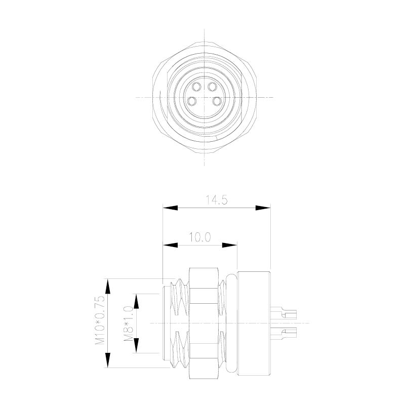


Unshielded straight-pin versions retain the 14.5mm rear-mounted or 16.0mm front-mounted body. The shielded rear version adds PCB shield contacts and has a different mounting cutout: Ø10.2mm(+0.1/0) with an 8.2mm(+0.1/0) flat-to-flat opening.


The shielded version uses a Ø10.2mm(+0.1/0) cutout with 9.2mm(+0.1/0) across its flats. The plastic configuration uses a round Ø8.1mm(+0.2/0) opening. Their PCB support and contact geometry differ.


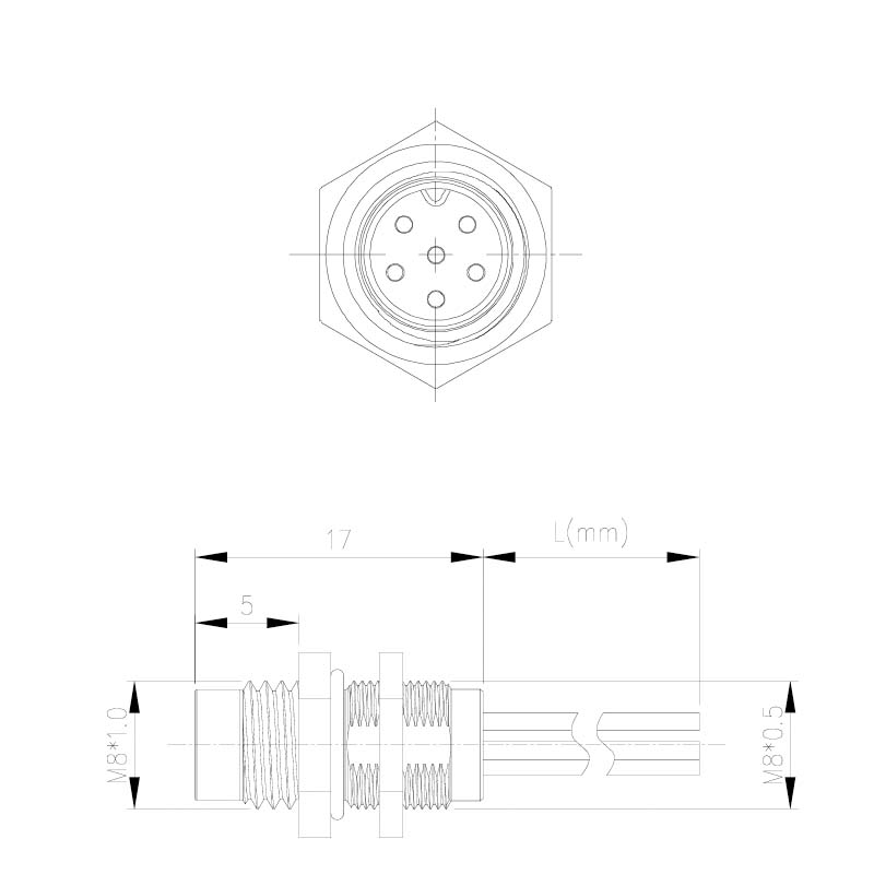
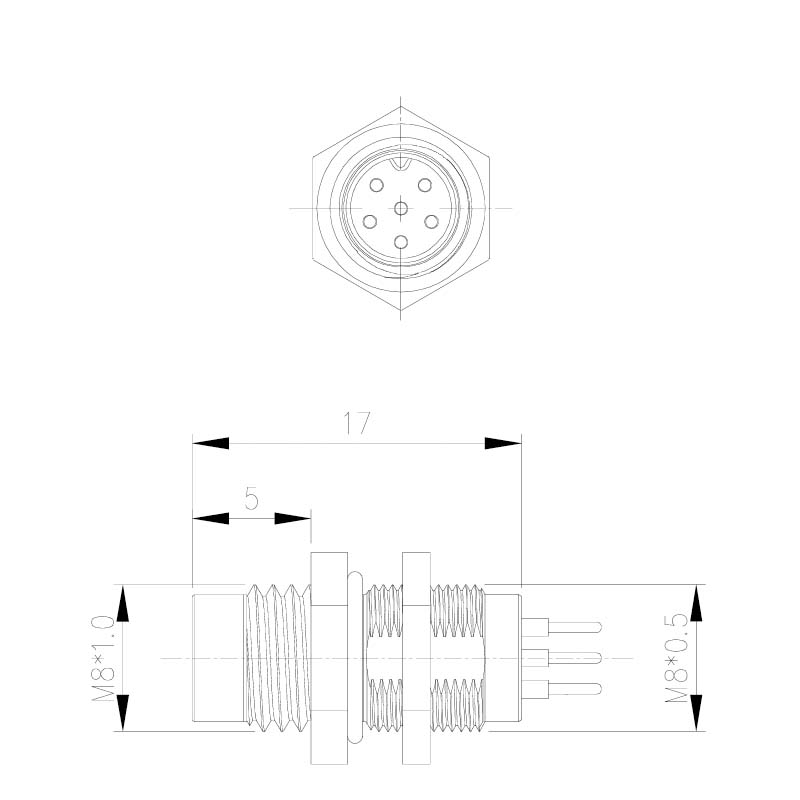
Male solder-cup and lead versions have 17mm bodies and Ø8.2±0.1mm panel cutouts. Rear-mounted versions use M8×1.0 mounting with 11.0mm and 14.0mm axial sections. Front-mounted versions separate the M8×1.0 mating thread from the M8×0.5 mounting thread and show a 5mm front section.


Unshielded front and rear versions use Ø8.2±0.1mm panel cutouts. The shielded rear version requires a Ø8.2mm(+0.1/0) opening with 7.2mm(+0.1/0) across the flats.

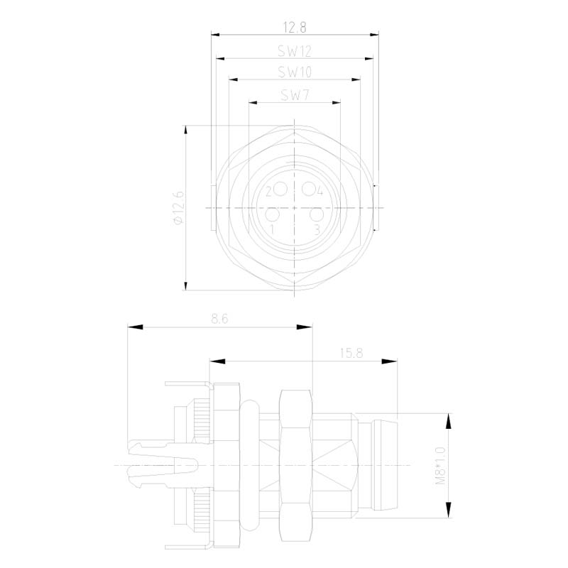
The shielded 90° version uses the Ø8.2mm(+0.1/0) cutout with 7.2mm(+0.1/0) flats. The plastic configuration uses a round Ø8.1mm(+0.2/0) opening.


Use the selected model's PDF for the complete numbered contact face, PCB support holes and terminal positions. Straight unshielded three-contact footprints specify Ø1.5mm contact holes; the other PCB configurations specify Ø1.30mm contact holes for 3, 4 or 5 contacts as applicable, and Ø0.90mm holes for 6 or 8 contacts. Shield contacts and plastic supports add mounting features; the footprints are not interchangeable.
| General dimension format | Tolerance |
|---|---|
| One decimal place, .X | ±0.3mm |
| Two decimal places, .XX | ±0.1mm |
| Angles | ±1° |
Explicit tolerances on panel openings take precedence over the general drawing tolerances. Outline dimensions describe the illustrated mounting configuration.
