
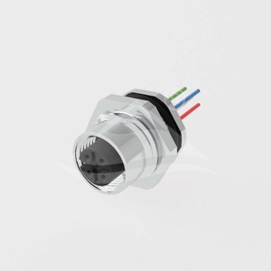
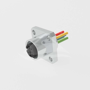
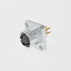
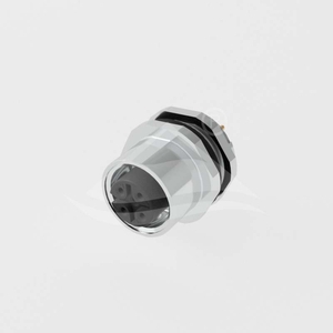
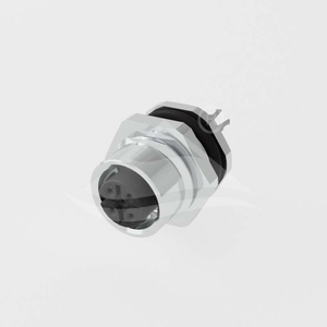

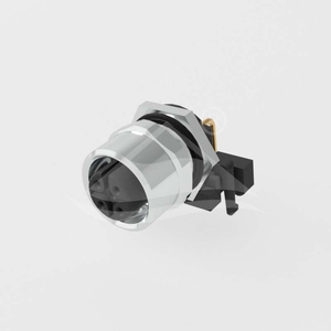
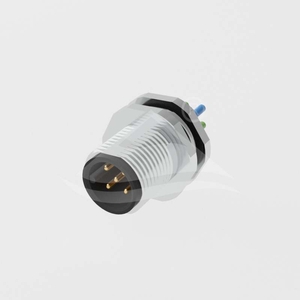
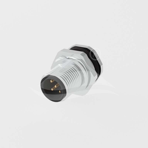

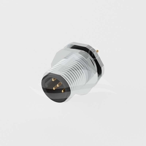
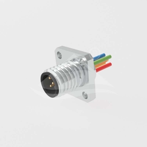
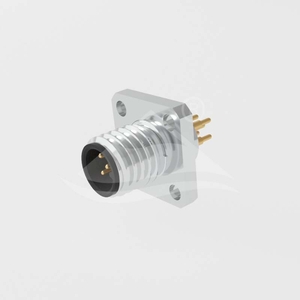
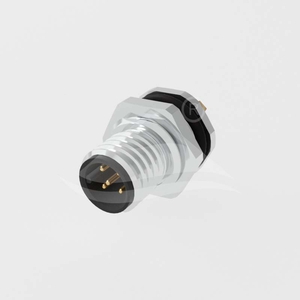
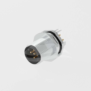

These receptacles provide an M12×1.0 mating interface for sensor and actuator connections. The range includes threaded front and rear panel mounting, four-hole square flanges, solder cups, individual wire leads and PCB terminals. Match the mating gender and coding before choosing the internal termination and panel opening.
| Model family | Mounting | Termination | A-coded contact counts |
|---|---|---|---|
| ULO-CC03-M12X-XXP-FF-SD-SF00X | Rear, PG9 or M16×1.5 | Solder cups | 3, 4, 5, 6, 8, 10, 12 |
| ULO-CC03-M12X-XXP-FF-SD-SFXXX | Rear, PG9 or M16×1.5 | Wire leads | 3, 4, 5, 6, 8, 10, 12 |
| ULO-CC03-M12X-XXP-FF-SD-SH00X | Front, PG9 or M16×1.5 | Solder cups | 3, 4, 5, 6, 8, 10, 12 |
| ULO-CC03-M12X-XXP-FF-SD-SHXXX | Front, PG9 or M16×1.5 | Wire leads | 3, 4, 5, 6, 8, 10, 12 |
| ULO-CC03-M12X-XXP-FF-SD-SS000 | Square flange | Solder cups | 3, 4, 5, 6, 8, 10, 12 |
| ULO-CC03-M12X-XXP-FF-SD-SS0XX | Square flange | Wire leads | 3, 4, 5, 6, 8, 10, 12 |
| ULO-CC03-M12X-XXP-FF-SP-SS000 | Square flange | 180° straight PCB pins | 3, 4, 5, 6, 8, 10, 12 |
| ULO-CC03-M12X-XXP-FF-SP-SF00X | Rear, PG9 or M16×1.5 | Unshielded straight PCB pins | 3, 4, 5, 6, 8, 10, 12 |
| ULO-CC03-M12X-XXP-FF-SP-SH00X | Front, PG9 or M16×1.5 | Unshielded straight PCB pins | 3, 4, 5, 6, 8, 10, 12 |
| ULO-CC03-M12X-XXP-FF-SPSH-SF00X | Rear, PG9 or M16×1.5 | Shielded straight PCB pins | 3, 4, 5, 6, 8, 12 |
| ULO-CC03-M12X-XXP-FF-SPSH-SH00X | Front, PG9 or M16×1.5 | Shielded straight PCB pins | 3, 4, 5, 6, 8, 12 |
| ULO-CC03-M12X-XXP-FF-ST-SF003 | Rear, round panel opening | Unshielded 90° PCB pins | 4, 5, 8, 12 |
| Model family | Mounting | Termination | A-coded contact counts |
|---|---|---|---|
| ULO-CC03-M12X-XXP-MM-SD-SF00X | Rear, PG9 or M16×1.5 | Solder cups | 3, 4, 5, 6, 8, 10, 12 |
| ULO-CC03-M12X-XXP-MM-SD-SH00X | Front, PG9 or M16×1.5 | Solder cups | 3, 4, 5, 6, 8, 10, 12 |
| ULO-CC03-M12X-XXP-MM-SD-SHXXX | Front, PG9 or M16×1.5 | Wire leads | 3, 4, 5, 6, 8, 10, 12 |
| ULO-CC03-M12X-XXP-MM-SP-SF00X | Rear, PG9 or M16×1.5 | 180° straight PCB pins | 3, 4, 5, 6, 8, 10, 12 |
| ULO-CC03-M12X-XXP-MM-SP-SFXXX | Rear, PG9 or M16×1.5 | Wire leads | 3, 4, 5, 6, 8, 10, 12 |
| ULO-CC03-M12X-XXP-MM-SP-SH00X | Front, PG9 or M16×1.5 | Unshielded straight PCB pins | 3, 4, 5, 6, 8, 10, 12 |
| ULO-CC03-M12X-XXP-MM-SD-SS000 | Square flange | Solder cups | 3, 4, 5, 6, 8, 10, 12 |
| ULO-CC03-M12X-XXP-MM-SD-SS0XX | Square flange | Wire leads | 3, 4, 5, 6, 8, 10, 12 |
| ULO-CC03-M12X-XXP-MM-SP-SS000 | Square flange | 180° straight PCB pins | 3, 4, 5, 6, 8, 10, 12 |
| ULO-CC03-M12X-XXP-MM-SPSH-SF00X | Rear, PG9 or M16×1.5 | Shielded straight PCB pins | 3, 4, 5, 6, 8, 12 |
| ULO-CC03-M12X-XXP-MM-SPSH-SH00X | Front, PG9 or M16×1.5 | Shielded straight PCB pins | 3, 4, 5, 6, 8, 12 |
| ULO-CC03-M12X-XXP-MM-ST-SF003 | Rear, round panel opening | Unshielded 90° PCB pins | 4, 5, 8, 12 |
All listed families also offer B-coded 5-contact and D-coded 4-contact arrangements. Shielding is expressly designated for SPSH models; do not infer shielding for other families where it is unspecified. ST right-angle versions have the narrower contact selection shown above.
| Coding and contacts | Rated current | Rated voltage | Withstand voltage |
|---|---|---|---|
| A, 3 or 4 contacts | 4A | 250V | 1500VAC |
| A, 5 contacts | 4A | 60V | 1200VAC |
| A, 6 or 8 contacts | 2A | 30V | 650V |
| A, 10 or 12 contacts | 1.5A | 30V | 500V |
| B, 5 contacts | 4A | 60V | 1120V |
| D, 4 contacts | 4A | 250V | 1500V |
Apply each rating only to a contact arrangement offered by the selected family. Withstand duration is unspecified; AC waveform is stated only for the 1500VAC A-coded 3/4-contact and 1200VAC A-coded 5-contact tests.
| Characteristic | Specification |
|---|---|
| Contact resistance | ≤3mΩ |
| Mating life | >50 insertion and withdrawal cycles |
| Protection rating | IP67 |
| Operating temperature | -40°C to +85°C |
| Contact material and surface | CuZn copper-zinc alloy with gold contact surface |
| Contact carrier | PA polyamide |
| Metal ring | Nickel-plated copper alloy |
| Seal | Silicone |
| Flammability classification | UL94V-0 |
| Compliance | RoHS |
Family identifiers contain placeholders for coding, contact count and applicable mounting or length options. The coding position is A, B or D; contact codes are 03, 04, 05, 06, 08, 10 and 12 where offered. Threaded solder-cup and PCB families use suffix 001 for PG9 or 002 for M16×1.5. Threaded wire-lead families use mounting code A for PG9 or B for M16×1.5. Square-flange SS models use their separate flange construction.
Wire-lead length codes apply to FF-SD-SFXXX, FF-SD-SHXXX, FF-SD-SS0XX, MM-SD-SHXXX, MM-SP-SFXXX and MM-SD-SS0XX. Cable jacket, conductor cross section and colour mapping are unspecified for these individual-lead versions.
| Lead-length code | Length |
|---|---|
| 15 | 150mm |
| 30 | 300mm |
| 50 | 500mm |
| A0 | 1000mm |
| A1 | 1100mm |
| B0 | 2000mm |
| B5 | 2500mm |
| Mounting construction | Main opening | Additional dimensions |
|---|---|---|
| PG9 threaded models | Ø15.4±0.1mm | 13.6±0.1mm across flats |
| M16×1.5 threaded models | Ø16.1±0.1mm | 13.6±0.1mm across flats |
| SS square-flange models | Ø12.1mm(+0.1/0) | 20mm × 20mm flange; four Ø3.2mm(+0.1/0) holes on 14±0.1mm × 14±0.1mm centres |
| ST right-angle models | Ø12.1mm(+0.1/0) | Separate PCB support footprint |
Threaded female bodies are 19.5mm long. Rear and front versions position the flange and seal differently, so select the correct installation direction even when their panel openings match.
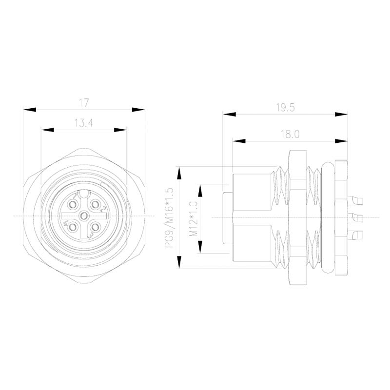


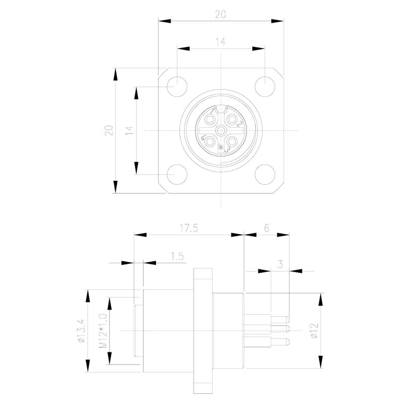
The female SS bodies are 17.5mm long with a 20mm square flange. Solder cups, leads and straight pins require different internal clearance.
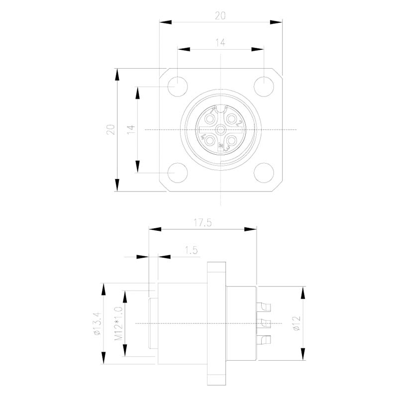
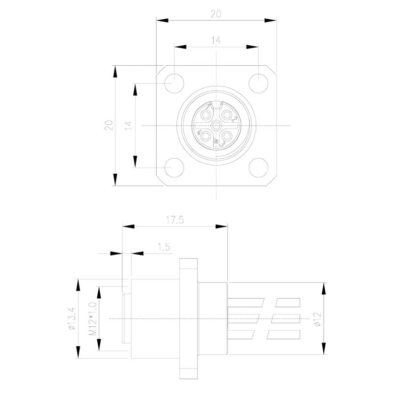
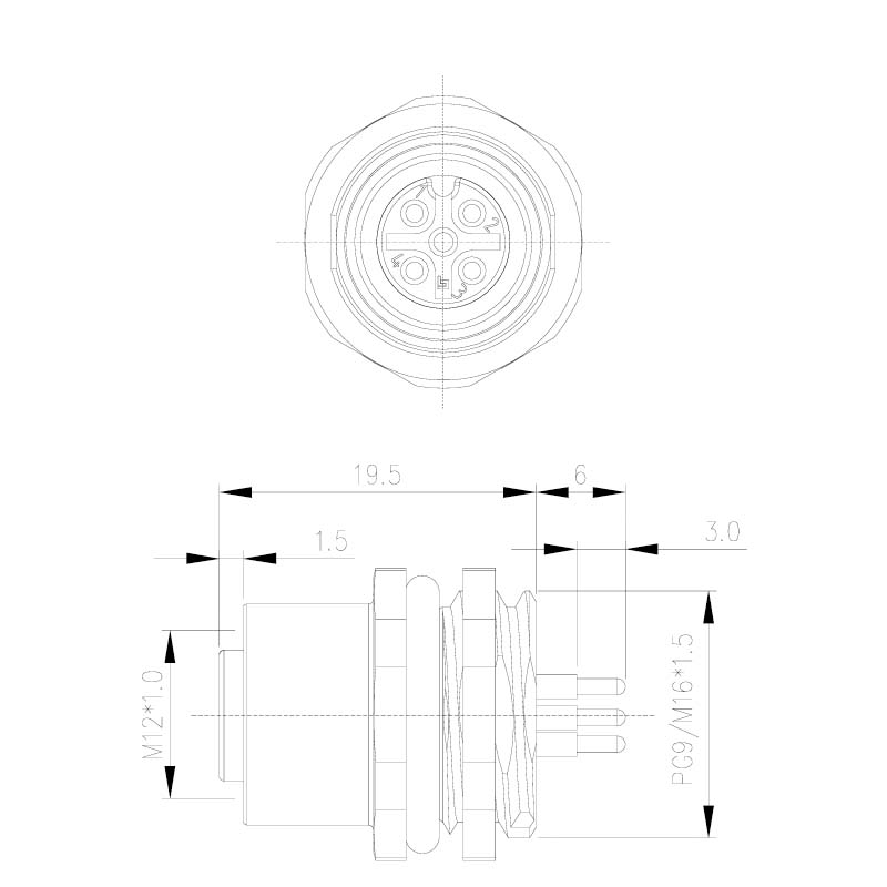
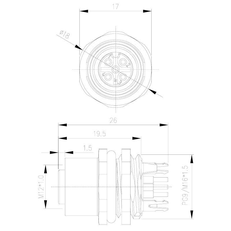
Unshielded straight-pin bodies are 19.5mm long with 6mm terminal projection. Shielded versions extend to 26mm overall and add PCB shield contacts.


The ST configuration uses a round panel opening and a separate support footprint, with contact positions arranged for a 90° connection to the PCB.

Rear-mounted male threaded bodies are 23mm long; front-mounted male bodies are 20mm long. Their external M12×1.0 mating thread is separate from the PG9 or M16×1.5 mounting designation.


Straight PCB versions have 6mm terminal projection and a 3mm terminal end section. The MM-SP-SFXXX family uses wire leads despite sharing the SP portion of its identifier.


The male SS configurations have 20mm bodies and 20mm square flanges. The 3mm rear section is shown separately from projecting terminals.


Shielded straight-pin versions add PCB shield contacts and have different overall lengths for front and rear mounting.


The male ST configuration has its own support and terminal footprint. Its body dimensions differ from the female right-angle version.

The model-specific PDFs show contact-face numbering and applicable PCB footprints. Three-contact A-coded faces use positions 1, 3 and 4; six-contact A-coded faces use positions 1, 2, 3, 4, 6 and 7. Preserve those physical contact numbers when connecting individual wires. Male and female faces are mirrored mating views. No wire-colour mapping is assigned here.
Shielded and right-angle PCB versions add mounting or shield terminals. Use the selected footprint for terminal holes and support features; body similarity does not establish a shared PCB layout.
| General drawing tolerance | Value |
|---|---|
| One decimal place, .X | ±0.3mm |
| Two decimal places, .XX | ±0.1mm |
| Angles | ±1° |
Explicit panel and footprint tolerances take precedence over the general drawing values. Body dimensions exclude lead length and projecting terminals unless identified as overall dimensions.
