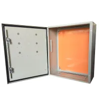


JXF wall mount enclosures provide a sheet steel housing for electrical controls, communications and distribution equipment. A polyurethane foam door gasket, removable mounting plate and gland plate support assembly and cable entry. Select the enclosure protection, coating and cable-entry arrangement for the installation environment.
IP65 and IP66 constructions are available. The IP66 configuration is specified with IK10 impact resistance, a 120° door opening and rear mounting holes for separately ordered wall brackets. Reserved hinge holes allow left or right door opening. The mounting plate has bent edges and raised fixing locations. Door reinforcement is provided on larger enclosures; configurations around 600mm high and above can include reinforcing profiles and zinc passivated rails.
| Parameter | Available specification |
|---|---|
| Body and door | Sheet steel; the standard size schedule below uses 1.2mm or 1.5mm. Other configurations offer 1.0mm or 2.0mm steel. |
| Mounting plate | Steel or galvanized steel; 2.0mm in the size schedule, with 1.5mm available in other configurations |
| Body finish | Textured thermosetting epoxy polyester powder coating |
| Enclosure color | RAL7032, RAL7035 or custom colors |
| Mounting plate finish | Flat powder coating in RAL2000 or silvery white galvanized finish |
| Included fittings | Gland plate, sealing gasket, earth-connection hardware and component mounting screws |
| Customization | Special dimensions, colors, display and control cutouts, cable openings and mounting arrangements |
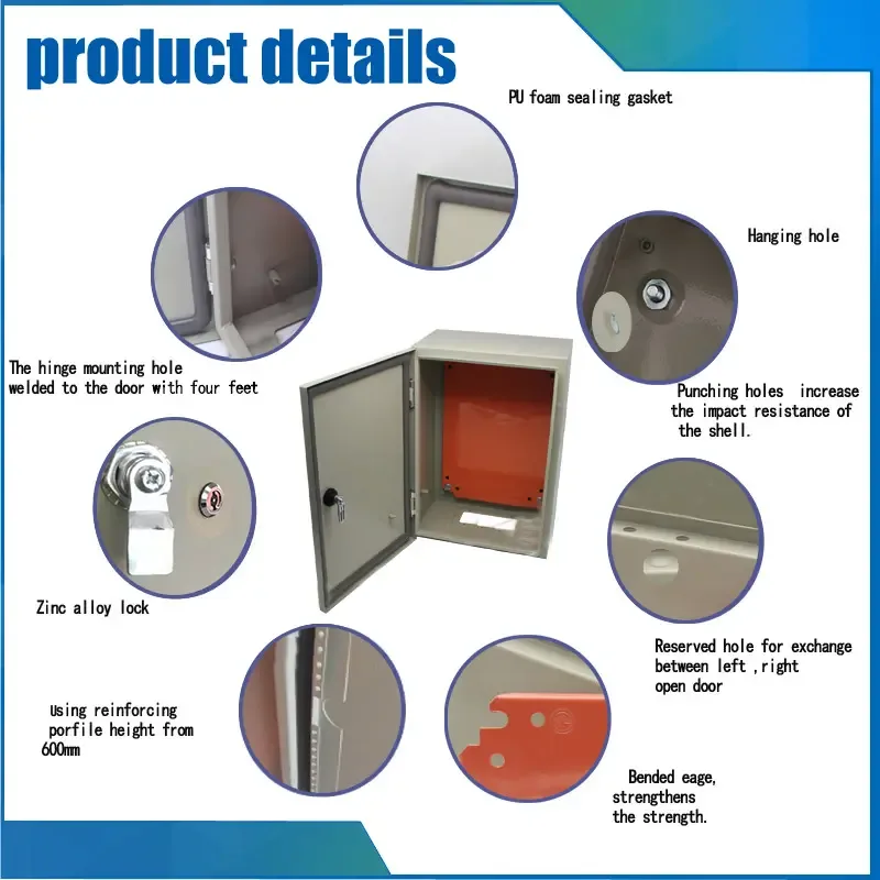

Dimensions and sheet thicknesses are in millimeters. Each depth listed in a row is a separate enclosure size sharing the other values in that row. L and M identify mounting plate height and width; cable-entry letters match the drawings below.
| H (mm) | W (mm) | Available D (mm) | Door / body thickness (mm) | Plate thickness (mm) | Entry type | Locks | Plate L × M (mm) |
|---|---|---|---|---|---|---|---|
| 200 | 200 | 150 | 1.2 / 1.2 | 2 | A | 1 | 150 × 150 |
| 250 | 200 | 150 | 200 × 150 | ||||
| 300 | 200 | 150, 200 | 250 × 150 | ||||
| 250 | 150, 200 | 250 × 200 | |||||
| 300 | 150, 200, 250 | B | 250 × 250 | ||||
| 400 | 300 | 150, 200, 250, 300 | 350 × 250 | ||||
| 400 | 150, 200, 250, 300 | C | 350 × 350 | ||||
| 500 | 300 | 150, 200, 250 | B | 450 × 250 | |||
| 400 | 150, 200, 250, 300 | C | 450 × 350 | ||||
| 500 | 200, 250, 300 | D | 450 × 450 | ||||
| 600 | 400 | 150, 200, 250, 300 | C | 2 | 550 × 350 | ||
| 500 | 150, 200, 250, 300 | D | 550 × 450 | ||||
| 600 | 150, 200, 250, 300 | 550 × 550 | |||||
| 700 | 500 | 150, 200 | 650 × 450 | ||||
| 600 | 200, 250 | 650 × 550 | |||||
| 300 | 1.5 / 1.5 | ||||||
| 800 | 600 | 200, 250, 300 | 750 × 550 | ||||
| 800 | 200, 250, 300 | F | 750 × 750 | ||||
| 1000 | 600 | 200 | D | 950 × 550 | |||
| 250, 300 | 3 | ||||||
| 700 | 200 | 950 × 650 | |||||
| 800 | 200, 250, 300, 400 | F | 950 × 750 | ||||
| 1000 | 250, 300 | G | 950 × 950 | ||||
| 1200 | 600 | 200, 250, 300 | D | 1150 × 550 | |||
| 800 | 200, 250, 300, 400 | F | 1150 × 750 | ||||
| 1000 | 250, 300, 400 | G | 1150 × 950 | ||||
| 1400 | 600 | 300 | D | 1350 × 550 | |||
| 800 | 300, 400 | F | 1350 × 750 | ||||
| 1000 | 300 | G | 1350 × 950 | ||||
| 1200 | 300 | 1350 × 1150 |


For a custom enclosure, provide the component layout or drawing, required material and thickness, cutouts, finish and installation details. Confirm the final construction and sample arrangement before production.
