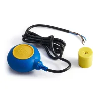


JK-M15 cable float switches provide level-operated switching for tank filling, drainage and low-water control. The float follows the liquid level and operates an internal contact mechanism. An adjustable cable anchor or optional counterweight establishes the switching band.
| Model | Illustrated body |
|---|---|
| JK-M15-1a | Black oval float |
| JK-M15-1b | Blue oval float |
| JK-M15-2a | Blue and yellow rectangular float |
| JK-M15-2b | Red and black rectangular float |
| JK-M15-3 | Blue and yellow circular float |
| JK-M15-4 | Red and black faceted float |
| JK-M15-5 | Blue bulb-shaped float |
| JK-M15-6 | Blue and yellow paddle-shaped float, shown with a cable reel |
| JK-M15-7 | Blue rounded rectangular float |

| Item | Selection information |
|---|---|
| General operating voltage | 200V |
| General operating current | Up to 10A; use the applicable contact and load rating of the selected construction |
| Control signal | Make/break contact action as the float changes position |
| Counterweight | Optional; supplied on request |
| Operating band | Adjusted through the cable fixing point or counterweight position |
Choose the float body, cable and contact arrangement for the liquid and load. Applications include water and selected wastewater, oil, dilute acid or alkaline service where the chosen materials are compatible. Food, drink and fuel applications require a construction suitable for that particular liquid; suitability is not established by float shape alone.
The illustrated three-wire changeover arrangement uses brown as the common conductor. The high-level position closes brown to black; the low-level position closes brown to blue. The unused conductor must be individually insulated.
| Control function | Conductors used | Low-level state | High-level state | Unused conductor |
|---|---|---|---|---|
| Tank emptying / drainage | Brown and black | Open: stop drainage | Closed: start drainage | Blue |
| Tank filling | Brown and blue | Closed: start filling | Open: stop filling | Black |
The action sketch shows approximate switching positions at 45° above and below horizontal, with the illustrated 280mm minimum clearance and 330mm minimum operating depth. The lower circuits operate a contactor; their coil label specifies a maximum of 250VAC. Select the actual contactor coil and pump circuit for the installation supply.

For a version fitted with a protective-earth conductor, the earth sheath is yellow/green and the remaining two working conductors provide the specified high-closure or low-closure function. This two-contact-lead construction differs from the illustrated three-working-wire changeover arrangement; select and identify the supplied cable configuration accordingly.

Secure the cable fixing point so the float can move without obstruction. To fit the optional counterweight, pass the cable through its conical opening and rotate the weight to release the retaining ring. Position the ring at the required point, then press and rotate the counterweight onto it.

Avoid joints in the regulator cable. Do not immerse a cable joint in the liquid. Direct pump switching is appropriate only within the actual unit's electrical rating; the contactor diagrams provide a separate pump-control arrangement.

