
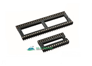
IC397 and IC398 sockets provide through-hole connections using stamped copper-alloy contacts and tin plating. IC397 has 2.54mm pitch; IC398 uses 1.778mm pitch. Select both the total contact count and the row spacing for the target IC and PCB layout.
| Model | Pitch | Contact counts | Row spacings | Terminal choices |
|---|---|---|---|---|
| ULO-IC397 | 2.54mm | 6, 8, 14, 16, 18, 20, 24, 28, 32, 40, 42 | 7.62mm or 15.24mm | Without kink or with kink |
| ULO-IC398 | 1.778mm | 24, 28, 30, 32, 40, 42, 48, 52, 56, 64 | 10.16mm, 15.24mm or 19.05mm | Straight terminals |
| Characteristic | Specification |
|---|---|
| Insulation resistance | ≥1000MΩ |
| Contact impedance | ≤20mΩ |
| Withstand test | 500VAC for 1 minute |
| Operating temperature | 0°C to +85°C |
| Storage temperature | -20°C to +70°C |
| Housing material | Thermoplastic |
| Insulating material group | I |
| Flammability classification | UL94V-0 |
| Contact material | Copper alloy |
| Contact finish | Tin |
| Rated operating voltage and current | Unspecified |
The 500VAC value is a one-minute withstand-test condition, not a continuous working-voltage rating.
| Field | Code and selection |
|---|---|
| Total contacts | 06, 08, 14, 16, 18, 20, 24, 28, 32, 40, 42 |
| Terminal form | A: without kink; B: with kink |
| Contact plating | T1: tin |
| Width D | N: 7.62mm for 6, 8, 14, 16, 18, 20, 24 or 28 contacts; W: 15.24mm for 24, 28, 32, 40 or 42 contacts |
| Central support | S: with support; X: without support |

The contact pitch is 2.54±0.1mm and terminal width is 0.60±0.05mm. Both section views show a 4.80mm housing dimension and 0.15±0.05mm terminal thickness. The straight form has a 3.0±0.3mm projecting terminal dimension; the kinked form has a 2.8mm projection and a 0.55mm reference offset.
A is body length, B is the distance between the end-contact centres, C is body width and D is row spacing. Table values are in millimetres.
| Contacts | A ±0.5mm | B ±0.20mm | C ±0.3mm | D |
|---|---|---|---|---|
| 6 | 7.62 | 5.08 | 10.16 | 7.62 |
| 8 | 10.16 | 7.62 | 10.16 | 7.62 |
| 14 | 17.78 | 15.24 | 10.16 | 7.62 |
| 16 | 20.32 | 17.78 | 10.16 | 7.62 |
| 18 | 22.86 | 20.32 | 10.16 | 7.62 |
| 20 | 25.40 | 22.86 | 10.16 | 7.62 |
| 24 | 30.48 | 27.94 | 10.16 | 7.62 |
| 24 | 30.48 | 27.94 | 17.78 | 15.24 |
| 28 | 35.56 | 33.02 | 10.16 | 7.62 |
| 28 | 35.56 | 33.02 | 17.78 | 15.24 |
| 32 | 40.64 | 38.10 | 17.78 | 15.24 |
| 40 | 50.80 | 48.26 | 17.78 | 15.24 |
| 42 | 53.34 | 51.00 | 17.78 | 15.24 |
The D tolerance is ±0.3mm for the straight-terminal section and ±0.2mm for the kinked-terminal section. These terminal-form conditions remain separate.

| Field | Code and selection |
|---|---|
| Total contacts | 24, 28, 30, 32, 40, 42, 48, 52, 56, 64 |
| Contact plating | T1: tin |
| Width D | N: 10.16mm; W: 15.24mm; D: 19.05mm |
| Central support | S: with support; X: without support |
The contact count determines the available row spacing as shown in the dimension table.
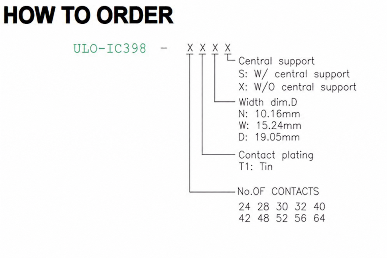
IC398 has 1.778±0.1mm contact pitch, 0.50±0.05mm terminal width and 0.15±0.05mm terminal thickness. The housing section is 4.8mm and the projecting terminal dimension is 3.0±0.3mm. Values below are in millimetres.
| Contacts | A ±0.3mm | B ±0.20mm | C ±0.20mm | D ±0.2mm |
|---|---|---|---|---|
| 24 | 21.34 | 19.56 | 12.65 | 10.16 |
| 28 | 24.89 | 23.11 | 12.65 | 10.16 |
| 30 | 26.67 | 24.89 | 12.65 | 10.16 |
| 32 | 27.45 | 26.67 | 12.65 | 10.16 |
| 40 | 35.56 | 33.78 | 17.73 | 15.24 |
| 42 | 37.34 | 35.56 | 17.73 | 15.24 |
| 48 | 42.67 | 40.89 | 17.73 | 15.24 |
| 52 | 46.23 | 44.45 | 17.73 | 15.24 |
| 56 | 49.78 | 48.01 | 17.73 | 15.24 |
| 64 | 56.90 | 55.12 | 21.54 | 19.05 |

