IC392, IC392A and IC392B provide distinct strip terminal constructions. Choose the pitch, number of rows and contact termination together. Each model lists 1×1 to 1×40 and 2×1 to 2×40 positions; the second number is the number of contacts per row.
Model
Pitch
Construction
Selection features
ULO-IC392
2.54mm
Through-hole straight-pin strip adapter
Four pin profiles; full gold flash
ULO-IC392A
2.0mm
Vertical, right-angle or SMT strip adapter
Single or dual rows; six finish options; black housing
ULO-IC392B
2.54mm
Solder-cup strip with PCB pins
Single or dual rows; six finish options; black housing
Common electrical and material data
Characteristic
Specification
Insulation resistance
≥1000MΩ
Contact impedance
≤20mΩ
Withstand test
500VAC for 1 minute
Operating temperature
0°C to +85°C
Storage temperature
-20°C to +70°C
Housing
Glass-filled PBT
Insulating material group
I
Flammability classification
UL94V-0
Contact material
Copper alloy
Rated operating current and voltage
Unspecified
The one-minute withstand test does not establish a continuous operating-voltage rating.
IC392 ordering and straight-pin profiles
Field
Code or choice
Positions
1×1 to 1×40; 2×1 to 2×40
Contact plating
F1: full gold flash
Contact type
1: type 1; 2: type 2; 3: type 3; 4: type 4
IC392 ordering fields for row count, plating and straight-pin profile.
Type
Overall length
Upper projection
Lower projection
Upper / lower diameter
Contact drawing reference
1
10.00mm
4.10mm
2.90mm
Ø0.46mm / Ø0.46mm
DS1006-12
2
11.96mm
4.00mm
4.96mm
Ø0.60mm / Ø0.46mm
DS1006-13
3
13.70mm
4.30mm
6.40mm
Ø0.60mm / Ø0.46mm
DS1006-14
4
11.80mm
4.40mm
4.40mm
Ø0.60mm / Ø0.50mm
DS1006-10
IC392 has a 3.00mm housing section, 2.54mm single-row width and 5.08mm dual-row width. Both longitudinal pitch and dual-row spacing are 2.54mm. For P contacts per row, overall strip length is P × 2.54mm ±0.5mm and end-contact span is (P − 1) × 2.54mm ±0.20mm. Pitch tolerance is ±0.1mm; the terminal-body section is Ø1.32mm ±0.1mm.
The recommended PCB pattern uses Ø0.80mm ±0.03mm holes on a 2.54mm grid, an end-hole span of (P − 1) × 2.54mm ±0.05mm and general layout tolerance ±0.05mm. Detailed contact outlines carry ±0.05mm general tolerance and a Ø1.78mm shoulder reference.
IC392 strip outlines, pin sections and recommended PCB hole layout.
All IC392A outlines show Ø0.47mm upper/contact pins and Ø0.50mm lower terminals. Longitudinal pitch is 2.00mm. For P positions per row, strip length is P × 2.0mm ±0.5mm. The dual-row SMT drawing expresses the same length as N/2 × 2.0mm ±0.5mm, where N counts all contacts in both rows.
IC392A mounting-specific outlines; the three mounting types have distinct lead geometry.
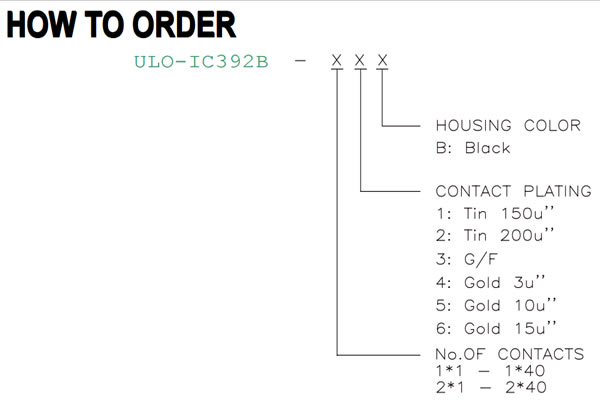
IC392B solder-cup terminal ordering
Field
Code or choice
Positions
1×1 to 1×40; 2×1 to 2×40
Contact plating
1: tin 150µin; 2: tin 200µin; 3: gold flash; 4: gold 3µin; 5: gold 10µin; 6: gold 15µin
Housing colour
B: black
IC392B ordering fields for solder-cup strips.
IC392B solder-cup and PCB pin dimensions
Feature
Dimension
Pitch
2.54mm ±0.1mm
Dual-row spacing
2.54mm
Single-row / dual-row body width
2.54mm / 5.08mm
Overall height
12.75mm
Housing height
3.00mm
Housing and lower shoulder reference
3.40mm
Lower PCB pin projection
4.25mm
PCB pin diameter
Ø0.45mm
Cup opening / outer diameter
Ø1.00mm / Ø1.81mm
Lower terminal-body diameter
Ø1.35mm ±0.1mm
Strip length for P contacts per row
P × 2.54mm ±0.2mm
IC392B single-row and dual-row solder-cup terminal outlines.