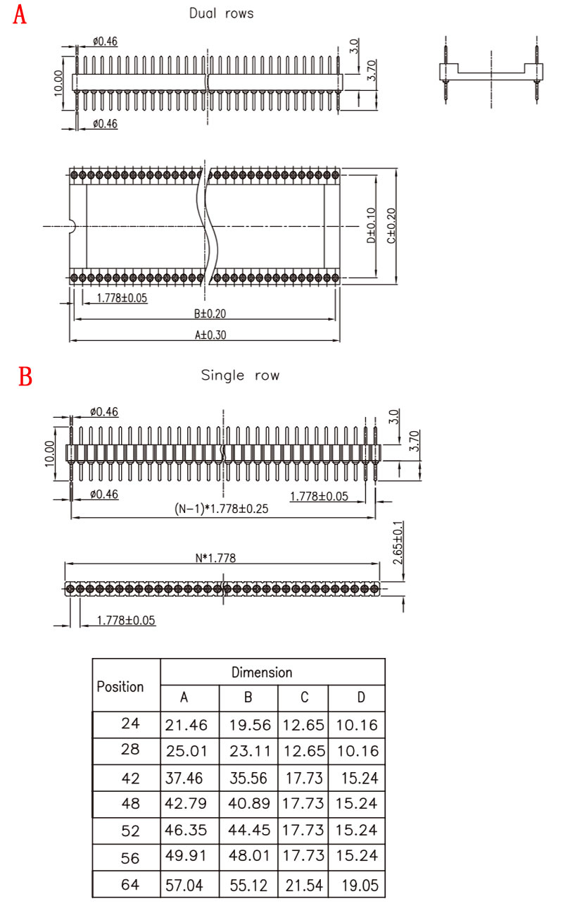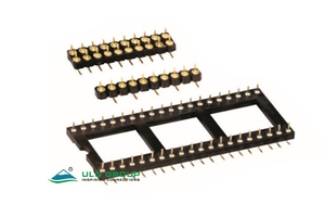
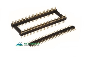
IC391A, IC391B and IC391C use machined male contacts. Select the pitch and frame or strip layout before choosing termination geometry and plating. The dimensional tables define supported framed combinations; strip counts refer to positions per row.
| Model | Pitch | Construction and row spacing | Housing |
|---|---|---|---|
| ULO-IC391A | 2.54mm | Framed header; straight and formed contact outlines; D = 7.62mm or 15.24mm | Glass-filled PBT |
| ULO-IC391B | 2.54mm | SMT framed header, D = 7.62mm or 15.24mm; single-row and dual-row strips | Thermoplastic |
| ULO-IC391C | 1.778mm | Through-hole framed header, D = 10.16mm, 15.24mm or 19.05mm; strip options | Glass-filled PBT |
| Characteristic | Specification |
|---|---|
| Insulation resistance | ≥1000MΩ |
| Contact impedance | ≤20mΩ |
| Withstand test | 500VAC for 1 minute |
| Operating temperature | 0°C to +85°C |
| Storage temperature | -20°C to +70°C |
| Insulating material group | I |
| Flammability classification | UL94V-0 |
| Contact material | Copper alloy |
| Rated operating current and voltage | Unspecified |
The one-minute withstand test is not a continuous operating-voltage rating.
| Field | Options |
|---|---|
| Total contacts | 6, 8, 14, 16, 18, 20, 24, 28, 32, 40; match the frame dimensions below |
| Row spacing D | N: 7.62mm; W: 15.24mm |
| Pin plating | F1: full gold flash |
| Contact type | 1: type 1; 2: type 2; 3: type 3 |
| Central support | S: with support; X: without support |

| Contact profile | Axial outline | Formed outline references |
|---|---|---|
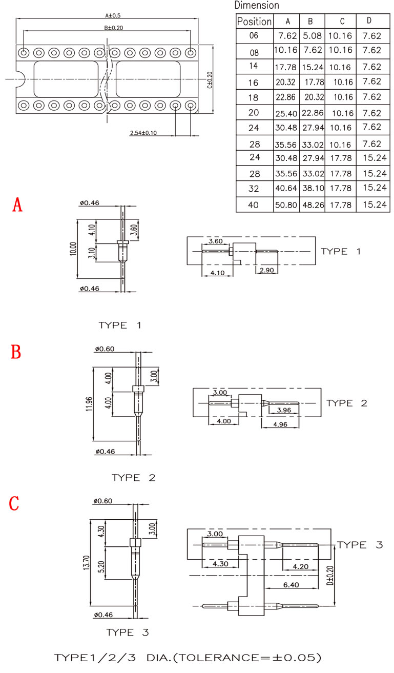
| Type 1 | 10.00mm overall; Ø0.46mm ends; 4.10mm and 3.10mm sections; 3.60mm upper reference | 4.10mm and 2.90mm sections; 3.60mm exposed reference |
| Type 2 | 11.96mm overall; Ø0.60mm upper and Ø0.46mm lower pin; two 4.00mm sections; 3.00mm upper reference | 4.00mm upper section; 4.96mm lower projection with 3.96mm exposed reference; 3.00mm upper reference |
| Type 3 | 13.70mm overall; Ø0.60mm upper and Ø0.46mm lower pin; 4.30mm and 5.20mm sections; 3.00mm upper reference | 4.30mm upper section; 6.40mm lower projection with 4.20mm exposed reference; formed row span D ±0.20mm |
Contact-profile dimensions use the illustrated ±0.05mm general tolerance except where another tolerance is marked. The contact-type drawings retain both axial and formed geometry references; match the required outline when specifying the header.
Values are in millimetres. A is overall length, B is end-contact span, C is outside frame width and D is row spacing. Pitch is 2.54mm ±0.10mm.
| Contacts | Width code | A ±0.5mm | B ±0.20mm | C ±0.20mm | D |
|---|---|---|---|---|---|
| 6 | N | 7.62 | 5.08 | 10.16 | 7.62 |
| 8 | N | 10.16 | 7.62 | 10.16 | 7.62 |
| 14 | N | 17.78 | 15.24 | 10.16 | 7.62 |
| 16 | N | 20.32 | 17.78 | 10.16 | 7.62 |
| 18 | N | 22.86 | 20.32 | 10.16 | 7.62 |
| 20 | N | 25.40 | 22.86 | 10.16 | 7.62 |
| 24 | N | 30.48 | 27.94 | 10.16 | 7.62 |
| 28 | N | 35.56 | 33.02 | 10.16 | 7.62 |
| 24 | W | 30.48 | 27.94 | 17.78 | 15.24 |
| 28 | W | 35.56 | 33.02 | 17.78 | 15.24 |
| 32 | W | 40.64 | 38.10 | 17.78 | 15.24 |
| 40 | W | 50.80 | 48.26 | 17.78 | 15.24 |
| Field | Options |
|---|---|
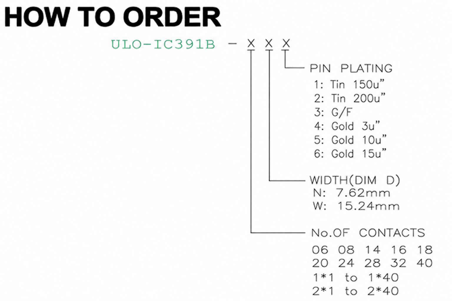
| Framed contact counts | 6, 8, 14, 16, 18, 20, 24, 28, 32, 40; use the dimensioned width combinations |
| Strip counts | 1×1 to 1×40; 2×1 to 2×40 |
| Framed row spacing D | N: 7.62mm; W: 15.24mm |
| Pin plating | 1: tin 150µin; 2: tin 200µin; 3: gold flash; 4: gold 3µin; 5: gold 10µin; 6: gold 15µin |
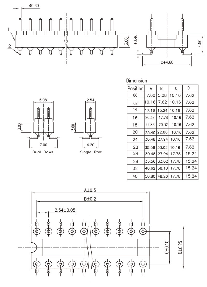
Values are in millimetres. A is overall length, B is end-contact span, C is outside frame width and D is framed row spacing. Pitch is 2.54mm ±0.05mm. The SMT frame has a 3.00mm body section, a 4.50mm mounting-height reference and a terminal span of C + 4.60mm. Upper pins are Ø0.60mm and formed lower pins are Ø0.46mm.
| Contacts | Width code | A ±0.5mm | B ±0.2mm | C ±0.10mm | D ±0.25mm |
|---|---|---|---|---|---|
| 6 | N | 7.60 | 5.08 | 10.16 | 7.62 |
| 8 | N | 10.16 | 7.62 | 10.16 | 7.62 |
| 14 | N | 17.16 | 15.24 | 10.16 | 7.62 |
| 16 | N | 20.32 | 17.78 | 10.16 | 7.62 |
| 18 | N | 22.86 | 20.30 | 10.16 | 7.62 |
| 20 | N | 25.40 | 22.86 | 10.16 | 7.62 |
| 24 | N | 30.48 | 27.94 | 10.16 | 7.62 |
| 28 | N | 35.56 | 33.02 | 10.16 | 7.62 |
| 24 | W | 30.48 | 27.94 | 17.78 | 15.24 |
| 28 | W | 35.56 | 33.02 | 17.78 | 15.24 |
| 32 | W | 40.62 | 38.10 | 17.78 | 15.24 |
| 40 | W | 50.80 | 48.26 | 17.78 | 15.24 |
The dual-row strip has a 5.08mm body width and 7.00mm terminal span; the single-row strip has a 2.54mm body width and 4.20mm terminal span. Both show a 3.00mm body section. These strip dimensions are separate from the framed N/W row-spacing choices.
| Field | Options |
|---|---|
| Framed contact counts | 24, 28, 42, 48, 52, 56, 64 |
| Strip counts | 1×1 to 1×40; 2×1 to 2×40 |
| Row and width code | S: single row, 1×1 to 1×40; 1: 10.16mm; 2: 15.24mm; 3: 19.05mm |
| Pin plating | 1: tin 150µin; 2: tin 200µin; 3: gold flash; 4: gold 3µin; 5: gold 10µin; 6: gold 15µin |
| Pin length | 1: 10.00mm |
The dual-row strip count range is listed separately from the framed dimensions. Its strip row spacing is not independently dimensioned.

Values are in millimetres. Pitch is 1.778mm ±0.05mm. A is overall length, B is end-contact span, C is outside frame width and D is row spacing.
| Contacts | Width code | A ±0.30mm | B ±0.20mm | C ±0.20mm | D ±0.10mm |
|---|---|---|---|---|---|
| 24 | 1 | 21.46 | 19.56 | 12.65 | 10.16 |
| 28 | 1 | 25.01 | 23.11 | 12.65 | 10.16 |
| 42 | 2 | 37.46 | 35.56 | 17.73 | 15.24 |
| 48 | 2 | 42.79 | 40.89 | 17.73 | 15.24 |
| 52 | 2 | 46.35 | 44.45 | 17.73 | 15.24 |
| 56 | 2 | 49.91 | 48.01 | 17.73 | 15.24 |
| 64 | 3 | 57.04 | 55.12 | 21.54 | 19.05 |
The framed and single-row outlines show 10.00mm overall pin length, Ø0.46mm pins, 3.0mm upper projection and a 3.70mm housing section. For a single row with N positions, overall length is N × 1.778mm and end-contact span is (N − 1) × 1.778mm ±0.25mm; body width is 2.65mm ±0.1mm.