
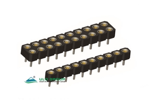
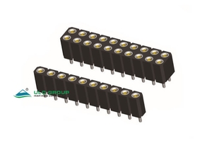
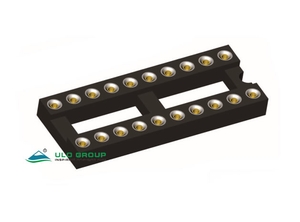
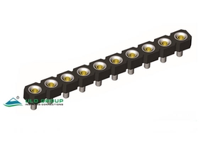
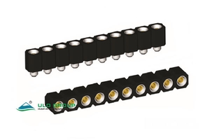
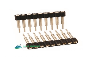
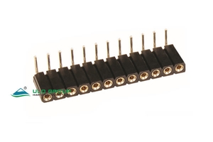

The IC390 family combines socket strips and the IC390D framed configuration. Select a model by pitch, body form and termination geometry before choosing pin and clip plating. Pin plating and the internal contact-clip finish are separate ordering fields.
| Model | Pitch | Listed counts | Configuration |
|---|---|---|---|
| ULO-IC390A | 2.54mm | 1×1 to 1×64; 2×1 to 2×40 | Vertical, right-angle or SMT strip |
| ULO-IC390B | 2.0mm | 1×1 to 1×40; 2×1 to 2×40 | Vertical strip with four-finger clip |
| ULO-IC390C | 2.54mm | 1×1 to 1×40; 2×1 to 2×40 | Vertical strip, 7.00mm housing and 10.00mm overall length |
| ULO-IC390D | 2.54mm | 6, 8, 14, 16, 18, 20, 24, 28, 32, 40 total contacts | Framed socket with 7.62mm or 15.24mm row spacing |
| ULO-IC390E | 2.54mm | 1×1 to 1×40 | Single-row short socket strip |
| ULO-IC390F | 2.54mm | 1×1 to 1×40; 2×2 to 2×40 | Extended terminal, two contact types and eight L choices |
| ULO-IC390G | 2.54mm | 1×1 to 1×40 | Extended terminal, two contact types and eight L choices |
| ULO-IC390H | 2.54mm | 1×1 to 1×40; 2×2 to 2×40 | Right-angle or SMT socket |
| ULO-IC390I | 2.0mm | 1×1 to 1×40; 2×2 to 2×40 | Right-angle or SMT socket |
| ULO-IC390J | 1.778mm | 6, 8, 14, 16, 18, 20, 24, 28, 32, 40 contacts | Single-row strip with three contact lengths |
For strip counts, the first number is rows and the second is positions per row. Dual-row availability is model-specific. In the dimensions below, P denotes positions per row; drawings may instead use N for either positions per row or total contacts, as indicated by their formulas.
| Characteristic | IC390A, B, C, D and J | IC390E, F, G, H and I |
|---|---|---|
| Insulation resistance | ≥1000MΩ | ≥1000MΩ |
| Contact impedance | ≤20mΩ | ≤20mΩ |
| Withstand test | 500VAC for 1 minute | 60VAC for 1 minute |
| Rated current | Unspecified | 3A |
| Average insertion force | Unspecified | ≤250gf |
| Average pullout force | Unspecified | ≥15gf |
| Operating temperature | 0°C to +85°C | Gold-plated: -55°C to +105°C; tinned: -40°C to +105°C |
| Storage temperature | -20°C to +70°C | -20°C to +70°C |
| Continuous operating-voltage rating | Unspecified | Unspecified |
Withstand values are one-minute test conditions. The E–I temperature ranges distinguish gold-plated and tinned versions; a separate limit for mixed pin/clip finishes is not defined. Force values are average insertion and withdrawal specifications, without a separately defined per-contact test basis.
| Material characteristic | All ten models |
|---|---|
| Housing | Glass-filled PBT |
| Insulating material group | I |
| Flammability classification | UL94V-0 |
| Contact material | Copper alloy |
The following six finish codes apply independently to both pin and clip plating on IC390A, C, D, F, G, H, I and J. IC390B and E use their own codes below.
| Code | Finish |
|---|---|
| 1 | Tin 150µin |
| 2 | Tin 200µin |
| 3 | Gold flash |
| 4 | Gold 3µin |
| 5 | Gold 10µin |
| 6 | Gold 15µin |
Mounting codes are V for vertical through-hole, R for right-angle through-hole and S for SMT. Choose pin and clip finishes independently from codes 1–6.

| Mounting | Body and height | Terminal geometry |
|---|---|---|
| Vertical | 3.00mm body height; 7.50mm overall; widths 2.54mm single row and 5.08mm dual row | Ø0.50mm ±0.05mm pin; Ø1.32mm ±0.1mm terminal-body reference |
| Right angle | 3.00mm body depth; 2.54mm single-row and 5.08mm dual-row body width | 5.60mm mounting reference; 3.20mm lower projection; Ø0.46mm terminal, with Ø0.51mm also marked on the outer dual-row terminal |
| SMT | 3.00mm body depth; 2.54mm single-row and 5.08mm dual-row body width | 5.60mm mounting reference; Ø0.50mm pins; terminal span 4.64mm single row or 7.30mm dual row |
Pitch and dual-row spacing are 2.54mm, with ±0.1mm where marked. Vertical strip length is P × 2.54mm ±0.5mm; right-angle and SMT length is P × 2.54mm without a separately marked overall tolerance. The dual-row SMT formula N/2 × 2.54mm counts total contacts in N.

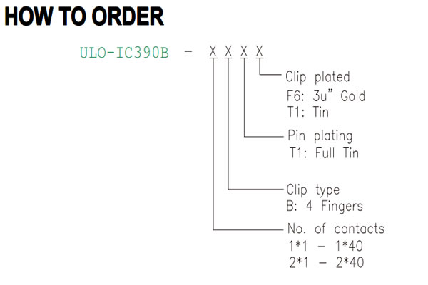
Clip type B has four fingers. Pin plating T1 is full tin; clip plating is F6 for 3µin gold or T1 for tin.
Single-row width is 2.20mm and dual-row width is 4.40mm. Both use 2.80mm housing height, 7.40mm overall height and Ø0.43mm pins. Longitudinal pitch and dual-row spacing are 2.00mm ±0.10mm. End offset is 1.00mm, and strip length is P × 2.0mm; the dual-row drawing expresses this as 2.0 × N/2 with N as total contacts.

Pin-length code 1 specifies 10.00mm overall length. Select pin and clip finishes independently with codes 1–6. Both single and dual rows have a 7.00mm housing section and Ø0.60mm PCB pins.

Pitch and dual-row spacing are 2.54mm. Body width is 2.54mm for a single row and 5.08mm for dual rows. Overall length is P × 2.54mm; end-contact span is (P − 1) × 2.54mm.

Width codes N and W select row spacing C of 7.62mm and 15.24mm respectively. Pin length F is 4.20mm. Pin and clip finishes use independent codes 1–6.

Values below are in millimetres. A is overall length, B is end-contact span, C is row spacing and D is outside frame width. Pitch is 2.54mm ±0.05mm. Housing height is 3.00mm and overall height is 4.20mm.
| Contacts | Width code | A ±0.3mm | B ±0.20mm | C ±0.10mm | D ±0.2mm |
|---|---|---|---|---|---|
| 6 | N | 7.62 | 5.08 | 7.62 | 10.16 |
| 8 | N | 10.16 | 7.62 | 7.62 | 10.16 |
| 14 | N | 17.78 | 15.24 | 7.62 | 10.16 |
| 16 | N | 20.32 | 17.78 | 7.62 | 10.16 |
| 18 | N | 22.86 | 20.32 | 7.62 | 10.16 |
| 20 | N | 25.40 | 22.86 | 7.62 | 10.16 |
| 24 | N | 30.48 | 27.94 | 7.62 | 10.16 |
| 28 | N | 35.56 | 33.02 | 7.62 | 10.16 |
| 24 | W | 30.48 | 27.94 | 15.24 | 17.78 |
| 28 | W | 35.56 | 33.02 | 15.24 | 17.78 |
| 32 | W | 40.64 | 38.10 | 15.24 | 17.78 |
| 40 | W | 51.00 | 48.26 | 15.24 | 17.78 |

Pin and clip plating are independent. Each uses 6 for full tin, 8 for full gold flash, C for full gold 3µin or A for full gold 10µin.

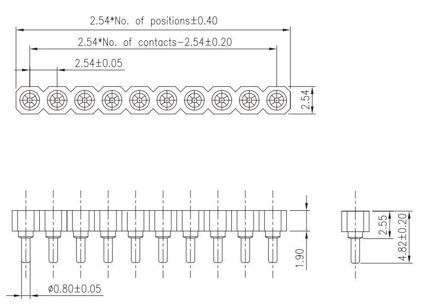
Body width is 2.54mm, housing/shoulder section is 2.55mm, overall height is 4.82mm ±0.20mm and the lower projection reference is 1.90mm. Pin diameter is Ø0.80mm ±0.05mm. Pitch is 2.54mm ±0.05mm; strip length is P × 2.54mm ±0.40mm and end-contact span is (P − 1) × 2.54mm ±0.20mm.
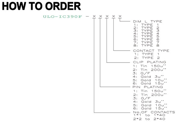
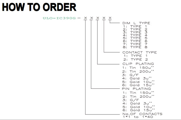
Both models offer contact type 1 or 2 and L codes 1–8. Pin and clip finishes are independently selected with codes 1–6. IC390F lists single and dual rows; IC390G lists single rows. The G drawing includes dual-row geometric references without a corresponding dual-row ordering range.
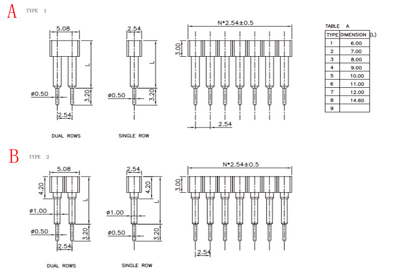
| L code | Dimension L for IC390F and G |
|---|---|
| 1 | 6.00mm |
| 2 | 7.00mm |
| 3 | 8.00mm |
| 4 | 9.00mm |
| 5 | 10.00mm |
| 6 | 11.00mm |
| 7 | 12.00mm |
| 8 | 14.60mm |
L is measured from the socket top to the start of the projecting PCB pin; the pin extends a further 3.20mm. Both types have Ø0.50mm PCB pins and a 3.00mm housing section. Type 2 adds an Ø1.00mm extended terminal section and a 4.20mm upper contact reference. Single-row body width is 2.54mm; the dual-row reference is 5.08mm with 2.54mm row spacing. Strip length is P × 2.54mm ±0.5mm.

Mounting codes are R for right angle and S for SMT. Profile code 420 is 4.20mm and 700 is 7.00mm. Both profiles are dimensioned for right-angle mounting; the SMT outline shows the 7.00mm profile. Pin and clip finishes use independent codes 1–6.

| Mounting and profile | Body and terminal references |
|---|---|
| Right angle, 4.20mm | 5.60mm mounting depth; 3.20mm lower projection; Ø0.60mm pins |
| Right angle, 7.00mm | 8.30mm mounting depth; 3.20mm lower projection; Ø0.60mm pins |
| SMT, 7.00mm | 8.80mm mounting depth; Ø0.60mm pins; 4.40mm single-row terminal span or 6.67mm dual-row terminal span |
Single-row body width is 2.54mm and dual-row width is 5.08mm. Pitch and dual-row spacing are 2.54mm ±0.1mm where marked. Strip length is P × 2.54mm ±0.5mm.
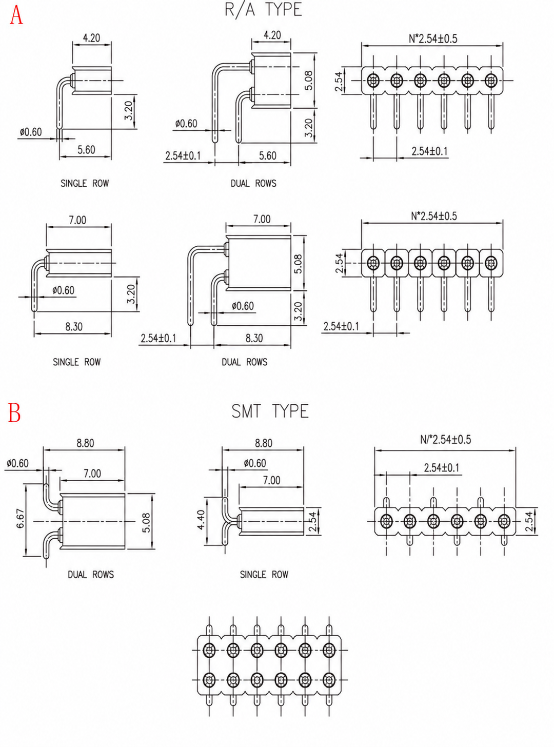
Choose R for right angle or S for SMT, with independent pin and clip plating codes 1–6.

| Feature | Right angle | SMT |
|---|---|---|
| Body depth | 2.80mm | 2.80mm |
| Single / dual-row body width | 2.20mm / 4.20mm | 2.20mm / 4.20mm |
| Mounting depth | 5.60mm | 5.80mm |
| Terminal diameter | Ø0.50mm | Ø0.50mm |
| Projection or terminal span | 3.20mm lower projection | 4.40mm single-row span; 6.40mm dual-row span |
Pitch and dual-row spacing are 2.00mm, with ±0.1mm where marked. Strip length is P × 2.0mm ±0.5mm. The dual-row SMT formula N/2 × 2.0mm ±0.5mm uses N as total contacts.

Contact codes 1, 2 and 3 select the following terminal outlines. Pin and clip finishes use independent codes 1–6. Listed contact counts are 6, 8, 14, 16, 18, 20, 24, 28, 32 and 40.

| Contact type | Length references | PCB pin diameter |
|---|---|---|
| 1 | 7.40mm overall | Ø0.45mm |
| 2 | 8.50mm to pin shoulder plus 3.20mm projecting pin | Ø0.53mm |
| 3 | 10.00mm to pin shoulder plus 4.00mm projecting pin | Ø0.53mm |
All three show 2.50mm body width, 3.00mm housing height and a 4.20mm upper contact reference. Pitch is 1.778mm and strip length is P × 1.778mm ±0.2mm.

