

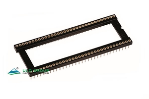
IC389 sockets use machined receptacle contacts in dual-row housings. IC389A and IC389C have straight through-hole terminals; IC389B has formed terminals for surface mounting. Contact pitch along a row and spacing between rows are separate selection dimensions.
| Model | PCB termination | Contact pitch | Row-spacing choices | Total contact counts |
|---|---|---|---|---|
| ULO-IC389A | Through-hole | 2.54mm | 7.62mm or 15.24mm | 6, 8, 14, 16, 18, 20, 24, 28, 32, 40 |
| ULO-IC389B | SMT | 2.54mm | 7.62mm or 15.24mm | 6, 8, 14, 16, 18, 20, 24, 28, 32, 40 |
| ULO-IC389C | Through-hole | 1.778mm | 10.16mm, 15.24mm or 19.05mm | 24, 28, 42, 48, 52, 56, 64 |
Use the model-specific width restrictions and dimension rows below; contact counts and widths are not freely interchangeable.
| Characteristic | Specification |
|---|---|
| Insulation resistance | ≥1000MΩ |
| Contact impedance | ≤20mΩ |
| Withstand test | 500VAC for 1 minute |
| Operating temperature | 0°C to +85°C |
| Storage temperature | -20°C to +70°C |
| Housing material | Glass-fibre-filled PBT |
| Insulating material group | I |
| Flammability classification | UL94V-0 |
| Contact material | Copper alloy |
| Rated operating voltage and current | Unspecified |
The withstand-test value does not establish a continuous operating-voltage rating. Pin plating and internal clip plating are separate ordering selections.
| Field | Code and selection |
|---|---|
| Contact counts | 06, 08, 14, 16, 18, 20, 24, 28, 32, 40 |
| Clip type | B: four fingers |
| Pin finish | T1: full tin; 8: full gold flash |
| Width | N: 7.62mm for 6, 8, 14, 16, 18, 20 or 24 contacts; W: 15.24mm for 24, 28, 32 or 40 contacts |
| Housing | S: PBT |
| Clip finish | F6: full 3µin gold; T1: tin |
| Central support | S: with support; X: without support |

A is body length, B is the end-contact centre distance, C is overall body width and D is row spacing. Table values are in millimetres. The pin diameter is Ø0.50±0.05mm and the larger contact section is Ø1.32±0.1mm. Overall axial length is 7.4mm, with a separate 4.5mm section dimension.
| Contacts | A ±0.5mm | B ±0.3mm | C | D ±0.2mm |
|---|---|---|---|---|
| 6 | 7.62 | 5.08 | 10.16 | 7.62 |
| 8 | 10.16 | 7.62 | 10.16 | 7.62 |
| 14 | 17.78 | 15.24 | 10.16 | 7.62 |
| 16 | 20.32 | 17.78 | 10.16 | 7.62 |
| 18 | 22.86 | 20.32 | 10.16 | 7.62 |
| 20 | 25.40 | 22.86 | 10.16 | 7.62 |
| 24 | 30.48 | 27.94 | 10.16 | 7.62 |
| 28, dimensional reference | 35.56 | 33.02 | 10.16 | 7.62 |
| 24 | 30.48 | 27.94 | 17.78 | 15.24 |
| 28 | 35.56 | 33.02 | 17.78 | 15.24 |
| 32 | 40.64 | 38.10 | 17.78 | 15.24 |
| 40 | 50.80 | 48.26 | 17.78 | 15.24 |
The 28-contact narrow-body row provides reference geometry; the IC389A ordering legend assigns the 28-contact order to the 15.24mm width group. The recommended PCB pattern uses 2.54mm pitch, Ø0.80±0.03mm holes and a separately marked B±0.1mm centre span, with a general layout tolerance of ±0.05mm.

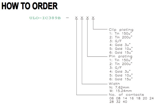
For IC389B and IC389C, the same numerical finish menu is available separately for pins and internal clips. These codes differ from IC389A.
| Finish code | Pin or clip finish |
|---|---|
| 1 | 150µin tin |
| 2 | 200µin tin |
| 3 | Gold flash |
| 4 | 3µin gold |
| 5 | 10µin gold |
| 6 | 15µin gold |
Width code N denotes 7.62mm and W denotes 15.24mm. The dimension table defines the supported count/width combinations, including the 28-contact narrow form. The formed terminal is Ø0.50mm; the side view marks a 5.33mm projection and a 3.00mm housing section.
| Contacts | A ±0.5mm | B ±0.2mm | C | D ±0.1mm | E ±0.3mm |
|---|---|---|---|---|---|
| 6 | 7.60 | 5.08 | 10.14 | 7.62 | 12.42 |
| 8 | 10.16 | 7.62 | 10.16 | 7.62 | 12.42 |
| 14 | 17.16 | 15.24 | 10.16 | 7.62 | 12.42 |
| 16 | 20.32 | 17.78 | 10.16 | 7.62 | 12.42 |
| 18 | 22.86 | 20.32 | 10.16 | 7.62 | 12.42 |
| 20 | 25.40 | 22.86 | 10.16 | 7.62 | 12.42 |
| 24 | 30.48 | 27.94 | 10.16 | 7.62 | 12.42 |
| 28 | 35.56 | 33.02 | 10.16 | 7.62 | 12.42 |
| 24 | 30.48 | 27.94 | 17.78 | 15.24 | 20.04 |
| 28 | 35.56 | 33.02 | 17.78 | 15.24 | 20.04 |
| 32 | 40.62 | 38.10 | 17.78 | 15.24 | 20.04 |
| 40 | 51.00 | 48.26 | 17.78 | 15.24 | 20.04 |
Values are in millimetres. E is the transverse span of the formed SMT terminals. C has no separate tolerance stated in this table.

IC389C uses width code N for 10.16mm, W for 15.24mm and D for 19.05mm. Available contact counts are 24, 28, 42, 48, 52, 56 and 64, with their width assignments shown below. Its straight pin diameter is Ø0.42mm and overall axial length is 7.40mm.

| Contacts | A ±0.30mm | B ±0.20mm | C ±0.20mm | D ±0.10mm |
|---|---|---|---|---|
| 24 | 21.46 | 19.56 | 12.65 | 10.16 |
| 28 | 25.01 | 23.11 | 12.65 | 10.16 |
| 42 | 37.46 | 35.56 | 17.73 | 15.24 |
| 48 | 42.79 | 40.89 | 17.73 | 15.24 |
| 52 | 46.35 | 44.45 | 17.73 | 15.24 |
| 56 | 49.91 | 48.01 | 17.73 | 15.24 |
| 64 | 57.04 | 55.12 | 21.54 | 19.05 |
Values are in millimetres. The section drawing also marks 3.0mm and 3.12mm housing dimensions and a 3.8mm edge width; these are separate features.

