

| Part Number: | ULO | - | DB426 | - | 15 | M | B | N | 8 | A | 4 | 4 |
|---|---|---|---|---|---|---|---|---|---|---|---|---|
| Explanation: |
Brand ULO - ULO |
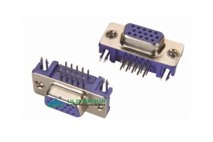
Model DB426 - Right-angle PCB |
Contacts 15 - 15 contacts; all models |
Connector Type M - Male; all models except DB426C |
Colour B - Black; all models |
Shell / Contact Plating N - Nickel shell; DB426, DB426A and DB426C |
Contact / Shell Plating Si - Selective gold flash; DB426, DB426A and DB426C |
Mounting Hardware A - With screw; DB426 and DB426A |
Boardlock F 4 - F=4.00mm; DB426 only |
Screw Dimension 4 - E=4.80mm; DB426; G=4.80mm; DB426A |
| Model | Termination and structure | Contact counts | Interface | Rated current | Rated voltage | Operating temperature |
|---|---|---|---|---|---|---|
| ULO-DB426 | Right-angle PCB | 15, 26, 44, 62 | Male or female | 1.5A | 250VAC | -45°C to +105°C |
| ULO-DB426A | Right-angle PCB, 15-contact body | 15 | Male or female | 1.5A | 250VAC | -20°C to +70°C |
| ULO-MP426B | Right-angle PCB, machined contacts | 15, 26, 44, 62 | Male or female | 5A | Unspecified | -45°C to +110°C |
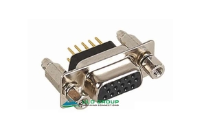
| ULO-DB426C | Slim right-angle PCB | 15 | Female | 1.5A | 250VAC | -45°C to +105°C |
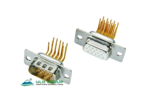
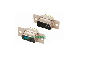
| ULO-DB465 | Straight through-hole PCB | 15, 26, 44, 62, 78 | Male or female | Unspecified | Unspecified | 0°C to +85°C |
| ULO-DB465A | Straight through-hole PCB with mounting-hardware options | 15, 26, 44, 62, 78 | Male or female | Unspecified | Unspecified | 0°C to +85°C |
Select the exact model before choosing the PCB footprint. The illustrated 15-contact interfaces use three rows; DB465 and DB465A also provide four-row 78-contact layouts. Straight and right-angle terminations have different tail geometry and mounting details.
| Characteristic | Value | Applicable models |
|---|---|---|
| Insulation resistance | ≥1000MΩ | All six |
| Contact impedance | ≤20mΩ | All six |
| Dielectric withstand test | 500VAC for 1 minute | All six |
| Insulation material group | I | All six |
| Material flammability grade | UL94V-0 | All six |
| Contact material | Copper alloy | All six |
| Insulator | Thermoplastic | DB426, DB426A, DB465 |
| Insulator | Glass-fibre-filled thermoplastic | MP426B, DB426C |
| Insulator | PBT with glass fibre | DB465A |
| Shell | Steel | DB426, DB426A, DB426C, DB465, DB465A |
| Shell | SPCC steel | MP426B |
| Boardlock, screw and rivet material | Copper alloy | DB426C |
| Durability | 500 cycles | MP426B |
| Retention | ≥1000gf | MP426B |
| Storage temperature | -20°C to +70°C | DB465, DB465A |
| Solder heat resistance | 260±5°C for 5±0.5s | DB465A |
The dielectric withstand value is a test condition. Apply only the current and working-voltage ratings listed for the selected model.
| Model | Interface code | Insulator colour codes | Contact plating codes | Shell plating codes |
|---|---|---|---|---|
| DB426 | M: male; F: female | Y: yellow; B: black; U: blue; C: blue (PC99) | Si: selective gold flash; 8: full gold flash; 6: full tin | N: nickel; T: tin |
| DB426A | M: male; F: female | B: black; U: blue; C: blue (PC99) | Si: selective gold flash; 8: full gold flash; 6: full tin | N: nickel; T: tin |
| MP426B | M: male; F: female | B: black; W: white; L: blue | 8: full gold flash; C: full 3µin gold | N: nickel front shell, tin back shell |
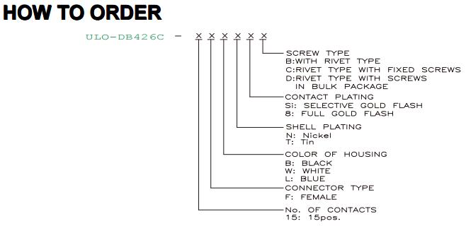
| DB426C | F: female | B: black; W: white; L: blue | Si: selective gold flash; 8: full gold flash | N: nickel; T: tin |
| DB465 / DB465A | M: male; F: female | B: black; W: white; U: blue | 8: full gold flash; 0: selective gold flash | T: tin front and back shells; N: nickel front shell, tin back shell |
Dimension letters in the hardware fields identify the corresponding screw or boardlock view, independently of the mating-outline dimension tables.
| Model | Hardware type codes | Screw dimension codes | Boardlock or mounting detail |
|---|---|---|---|
| DB426 | A: screw; B: rivet; C: rivet with fixed screws; D: rivet with screws supplied in bulk | E: code 4 = 4.80mm; 5 = 5.80mm | F: code 4 = 4.00mm; 7 = 3.70mm |
| DB426A | A: screw; B: rivet; C: screw and rivet | G: code 4 = 4.80mm; 5 = 5.80mm | F: code 7 = 3.70mm |
| MP426B | S: standard without nut; 1: CC | A: S = standard without nut; 1 = 5.00mm; 2 = 3.00mm; 3 = 5.20mm; 4 = 4.80mm; 5 = 5.80mm; 6 = 3.80mm | Standard and CC profiles |
| DB426C | B: rivet; C: rivet with fixed screws; D: rivet with screws supplied in bulk | No separate screw-size field | Slim mounting profile |
| DB465 | S: standard without nut; 1: CC; 2: CS; 3: BR; 4: BRJ with C = 3-4mm; 5: BRJ with C = 5-6mm; 6: BRJ with C = 3-4mm and screws supplied in bulk | A: S = standard without nut; 1 = 5.00mm; 2 = 3.00mm; 3 = 5.20mm; 4 = 4.80mm; 5 = 5.80mm; 6 = 4.00mm | BR and BRJ drawings show a 6.00mm reference |
| DB465A | X: without fork; 3: BR; 4: BRJ without washer; 7: BRJ with washer | A: X = without screw; 4 = 4.80mm; 5 = 5.80mm | BR and BRJ mounting forms, UNC #4-40 |
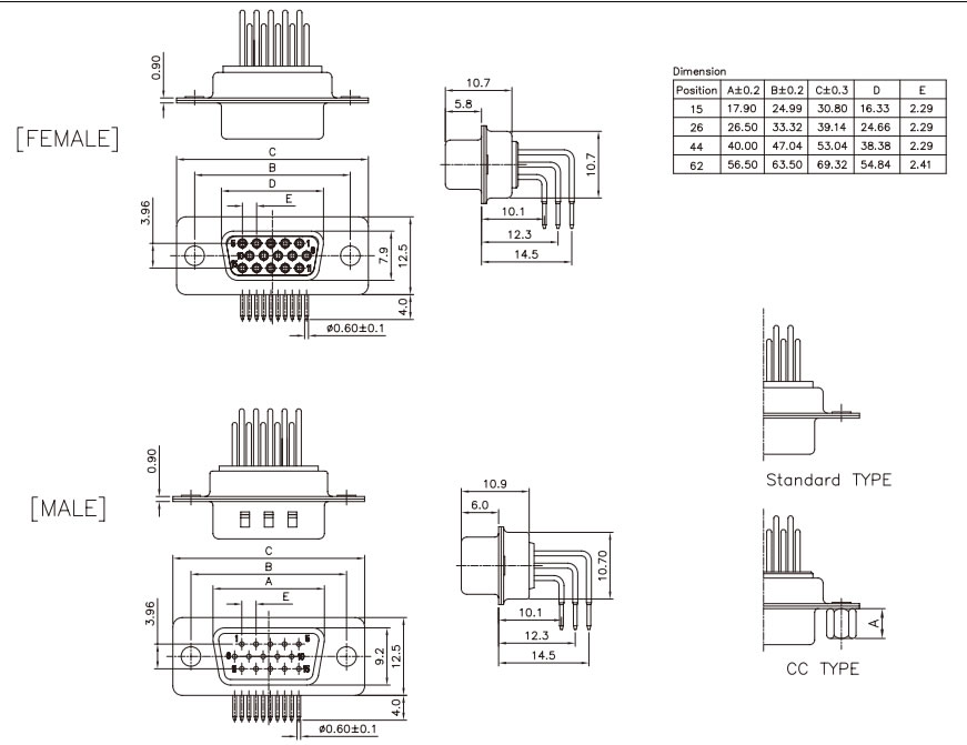
Values are in millimetres. A is male mating width, B mounting centres, C flange length, D female mating width and E the contact-pitch reference. The two models retain their own flange-length nominal for 15 contacts.
| Contacts | A ±0.2 | B ±0.2 | C ±0.3, DB426 | C ±0.3, MP426B | D | E |
|---|---|---|---|---|---|---|
| 15 | 17.90 | 24.99 | 30.84 | 30.80 | 16.33 | 2.29 |
| 26 | 26.50 | 33.32 | 39.14 | 39.14 | 24.66 | 2.29 |
| 44 | 40.00 | 47.04 | 53.04 | 53.04 | 38.38 | 2.29 |
| 62 | 56.50 | 63.50 | 69.32 | 69.32 | 54.84 | 2.41 |
DB426 shows 22.0mm female and 22.2mm male side-profile depth references, 6.3mm and 6.5mm mating projections, and 3.3mm and 3.5mm tail references respectively. The side profiles also identify 13.71mm, 11.17mm and 8.63mm dimensions. The illustrated top-side PCB pattern uses Ø1.00mm contact holes, Ø3.05mm mounting holes, a 5.08mm row-span reference and a 0.25mm stagger reference, with ±0.05mm layout tolerance.


DB426A is available with male or female 15-contact interfaces. The drawing gives a 30.80mm flange length, 24.99mm mounting centres, 16.36mm female and 17.13mm male mating-width references, 2.29mm contact pitch and a 3.96mm mating-row span. Side profiles show a 15.00mm depth reference and 6.10mm mating projection. Tail-position references are 3.08mm, 5.06mm and 7.04mm; the illustrated top-side PCB patterns retain their gender-specific orientation and ±0.05mm tolerance.


MP426B uses 5A machined contacts and right-angle tails. The three tail-position references are 10.1mm, 12.3mm and 14.5mm. Both genders show Ø0.60±0.1mm tails, 4.0mm tail length and a 10.7mm height reference. Female and male mating projections are 5.8mm and 6.0mm respectively, with 10.7mm and 10.9mm side references and a 0.90mm step.

DB426C has a 15-contact female interface, 30.80mm flange length, 24.99mm mounting centres and a 16.40mm mating-width reference. It shows a 5.90mm body-height reference, 3.40mm contact-tail and 2.50mm mounting-tail references, and a 1.50mm side offset. The fixed-screw view identifies 11.8mm and 4.8mm hardware dimensions.
The PCB drawing includes 30.73mm mounting span, 19.05mm and 10.68mm intermediate spans, 0.76mm contact spacing and 0.13mm stagger references. It separately identifies two Ø1.80mm and two Ø0.93mm mounting features, 3.30mm, 2.51mm, 2.00mm and 1.50mm references, and ±0.05mm layout tolerance. Use this slim footprint for DB426C.

Values are in millimetres. A is male mating width, B mounting centres, C flange length, E female mating width and F the indicated contact pitch.
| Contacts | A | B | C | E | F |
|---|---|---|---|---|---|
| 15 | 17.90 | 24.99 | 30.80 | 16.33 | 2.29 |
| 26 | 26.50 | 33.32 | 39.14 | 24.66 | 2.29 |
| 44 | 40.00 | 47.04 | 53.04 | 38.38 | 2.29 |
| 62 | 56.50 | 63.50 | 69.32 | 54.84 | 2.41 |
| 78 | 54.30 | 61.00 | 67.04 | 52.34 | 2.41 |
The 78-contact views show four rows with 2.05mm row spacing, a 6.15mm row span and a 15.30mm flange height. The female mating-height reference is 10.80mm and the male reference is 12.20mm. The illustrated 15-contact views instead show a 3.96mm row span and 12.50mm flange height.
DB465 shows 4.4mm tail references, a 10.70mm side reference and a 0.90mm step. Female and male height references are 10.7mm and 11mm respectively. Select the standard, CC, CS, BR or BRJ hardware profile using the model's ordering fields.


DB465A shows 4.10mm tail references, a 9.20mm body-height reference and a 0.70mm step. Its mounting options include BR and BRJ profiles with or without a washer. The two 78-contact detail views are labelled individually as female and male.


