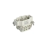


HE screw-terminal inserts provide rectangular male and female connections for industrial equipment. Choose 6, 10, 16 or 24 contacts in a single insert, or a 32- or 48-contact arrangement built from two inserts. Each arrangement includes protective-earth connections and uses the corresponding B-size hood and housing.
| Contacts, plus PE | Male model | Female model | Hood and housing size | Insert arrangement |
|---|---|---|---|---|
| 6 | SO-HE-006-M | SO-HE-006-F | H6B | One insert, positions 1-6 |
| 10 | SO-HE-010-M | SO-HE-010-F | H10B | One insert, positions 1-10 |
| 16 | SO-HE-016-M | SO-HE-016-F | H16B | One insert, positions 1-16 |
| 24 | SO-HE-024-M | SO-HE-024-F | H24B | One insert, positions 1-24 |
| 32 | SO-HE-032-M | SO-HE-032-F | H32B | Two 16-contact inserts, positions 1-16 and 17-32 |
| 48 | SO-HE-048-M | SO-HE-048-F | H48B | Two 24-contact inserts, positions 1-24 and 25-48 |
Select matching contact counts and complementary male and female inserts. Hood entry, mounting style, cable gland and enclosure sealing are separate selections; the insert alone does not establish an assembled connector's ingress-protection rating.
| Rating condition | Current | Voltage | Impulse voltage | Pollution degree |
|---|---|---|---|---|
| EN 61984 | 16A | 500V | 6kV | 3 |
| Additional pollution-degree-2 rating | 400/690V | 2 |
| Property | Specification |
|---|---|
| Rated voltage according to UL/CSA | 600V |
| Insulation resistance | ≥1010Ω |
| Insert material | Polycarbonate |
| Insert colour | RAL 7032 light grey |
| Temperature range | -40°C to +125°C |
| Flammability according to UL 94 | V0 |
| Mechanical life | ≥500 mating cycles |
| Contact material | Copper alloy |
| Contact resistance | ≤1mΩ |
| Contact surface | Hard-silver plated for the illustrated M/F models. Hard-gold plating is a separate option whose availability must be specified for the selected order. |
The M and F models use screw terminals. Match the conductor cross-section to the terminal range, strip the conductor to the specified length and tighten the connection to the stated torque.
| Applicable models | Conductor cross-section | Wire size | Stripping length | Tightening/test torque |
|---|---|---|---|---|
| All M/F models listed above | 0.14-2.5mm² | 26-14AWG | 7.0mm | 0.5N·m |
Length, width and height below describe one insert block. For the 32- and 48-contact models, use the paired arrangement and the corresponding panel-cutout drawing when planning the complete installation.
| Model | Block length | Block width | Block height | Longitudinal fixing pitch |
|---|---|---|---|---|
| SO-HE-006-M | 51mm | 34mm | 32.5mm | 44mm |
| SO-HE-006-F | 34.55mm | |||
| SO-HE-010-M | 64.10mm | 32.40mm | 57mm | |
| SO-HE-010-F | 64.20mm | 34.55mm | ||
| SO-HE-016-M | 84.30mm | 32.5mm | 77.50mm | |
| SO-HE-016-F | 84.20mm | 34.70mm | ||
| SO-HE-024-M | 111mm | 32.35mm | 104mm | |
| SO-HE-024-F | 34.55mm | |||
| SO-HE-032-M | 84.30mm | 32.5mm | 77.50mm | |
| SO-HE-032-F | 84.20mm | 34.70mm | ||
| SO-HE-048-M | 111mm | 32.35mm | 104mm | |
| SO-HE-048-F | 34.55mm |
A separate drawing is available for each male and female model, with contact numbering, side views and panel-cutout geometry. Match the complete model suffix when choosing the installation drawing.
