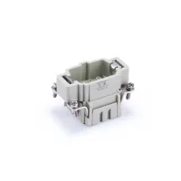
HE crimp-terminal inserts use removable crimp contacts in male MC and female FC bodies. Four contact counts cover 6, 10, 16 and 24 positions plus protective earth. Select the insert size, contact gender, conductor size and contact finish together when specifying a cable assembly.
Insert models
| Contacts, plus PE | Male insert | Female insert | Hood and housing size |
|---|
| 6 | SO-HE-006-MC | SO-HE-006-FC | H6B |
| 10 | SO-HE-010-MC | SO-HE-010-FC | H10B |
| 16 | SO-HE-016-MC | SO-HE-016-FC | H16B |
| 24 | SO-HE-024-MC | SO-HE-024-FC | H24B |
The MC/FC suffix identifies crimp termination. Choose a complementary male and female pair with the same contact count, then select the required hood entry, housing mounting style and cable gland.
Crimp contacts and wire preparation
| Property | Specification | Selection condition |
|---|
| Termination | Crimp | MC male and FC female inserts |
|---|
| Conductor range | 0.14-4.0mm² | Combined range of available contact sizes; select a contact suitable for the actual conductor. |
|---|
| Wire size | 26-12AWG | Match the wire size to the chosen crimp contact. |
|---|
| Stripping length | 7.5mm | All listed MC/FC models |
|---|
| Contact material | Copper alloy | Crimp contacts |
|---|
| Contact finishes | Hard-silver plated or hard-gold plated | Specify the required finish and contact size when ordering; the insert model alone does not identify plating. |
|---|
| Contact resistance | ≤1mΩ | Mated contact connection |
|---|
| Crimp contact tool | TL02G | Listed for the 6-, 10- and 24-contact MC/FC models; match tooling to the selected contact. |
|---|
| Contact removal tool | TL01 | Listed for the 6-, 10- and 24-contact MC/FC models. |
|---|
Prepare and crimp each conductor with tooling matched to its contact. Check contact retention after insertion into the body. Tool selection for the 16-contact inserts depends on the contacts specified for the assembly.
Electrical and material specifications
| Rating condition | Current | Voltage | Impulse voltage | Pollution degree |
|---|
| EN 61984 | 16A | 500V | 6kV | 3 |
| Additional pollution-degree-2 rating | 400/690V | 2 |
| Property | Specification |
|---|
| Rated voltage according to UL/CSA | 600V |
|---|
| Insulation resistance | ≥1010Ω |
|---|
| Insulating body | Polycarbonate, RAL 7032 light grey |
|---|
| Temperature range | -40°C to +125°C |
|---|
| Flammability according to UL 94 | V0 |
|---|
| Mechanical life | ≥500 mating cycles |
|---|
Dimensions and mounting
| Model | Length | Width | Height | Longitudinal fixing pitch |
|---|
| SO-HE-006-MC | 51mm | 34mm | 33mm | 44mm |
| SO-HE-006-FC | 35mm |
| SO-HE-010-MC | 64mm | 33mm | 57mm |
| SO-HE-010-FC | 35.2mm |
| SO-HE-016-MC | 84.5mm | 33.5mm | 77.5mm |
| SO-HE-016-FC | 35mm |
| SO-HE-024-MC | 111mm | 33.5mm | 104mm |
| SO-HE-024-FC | 35.5mm |
Each MC and FC model has its own drawing showing the contact layout, insert outline and panel cutout. Use the drawing for the complete model number when checking mounting clearances and contact orientation.