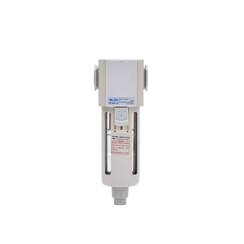
GF air filters use a swirling air path to separate liquid from compressed air while the element captures solid particles. The GF200, GF300 and GF400 body sizes offer different flow ratings and drain-bowl capacities, with PT connections from 1/8″ to 1/2″.
| Model | Port P | Maximum flow, L/min (ANR) | Drain bowl | Bowl guard |
|---|---|---|---|---|
| GF200-06 | PT1/8 | 3000 | 10mL | Without |
| GF200-08 | PT1/4 | |||
| GF300-08 | PT1/4 | 5000 | 40mL | Iron guard |
| GF300-10 | PT3/8 | |||
| GF300-15 | PT1/2 | |||
| GF400-10 | PT3/8 | 8000 | 80mL | |
| GF400-15 | PT1/2 |
In GF300-10, G identifies the series, F the filter function, 300 the body size and 10 the 3/8″ port. The other port codes are 06 for 1/8″, 08 for 1/4″ and 15 for 1/2″.
| Parameter | Specification |
|---|---|
| Working pressure | 0.15-0.9MPa |
| Ambient temperature | -5-60°C |
| Filtration | 40μm standard; 5μm optional |
| Body material | Aluminum alloy |
| Bowl material | PC |
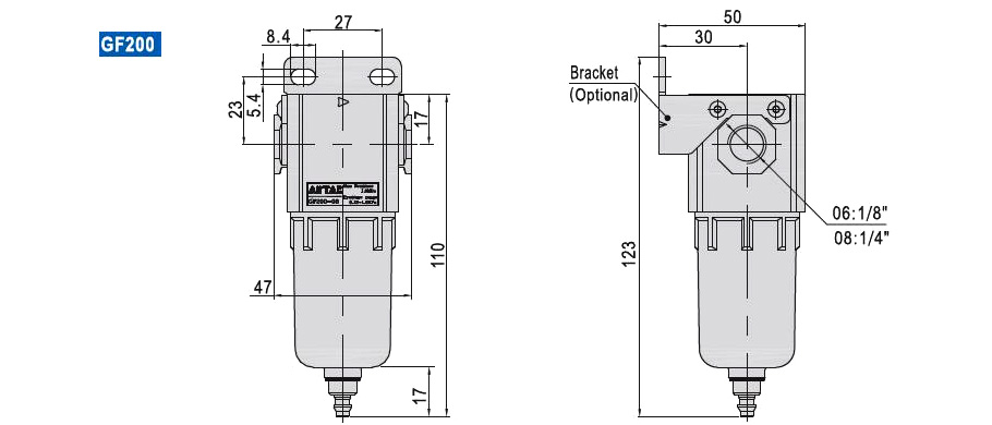
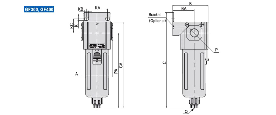
The following dimensions are common to models within each body-size group. Port P is listed separately in the model-selection table.
| Models | A | B | BA | C | CA | K | KA | KB | KC | Q |
|---|---|---|---|---|---|---|---|---|---|---|
| GF200-06/08 | 47 | 50 | 30 | 123 | 110 | 5.4 | 27 | 8.4 | 23 | — |
| GF300-08/10/15 | 60 | 67.5 | 41 | 182 | 164 | 6.5 | 40 | 8 | 27 | G1/8 |
| GF400-10/15 | 80 | 85.5 | 50 | 208 | 191.5 | 8.5 | 55 | 11 | 33.5 | G1/4 |
The attached Pneumatic Components Catalogue includes the GF range and related air preparation components.
