
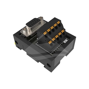
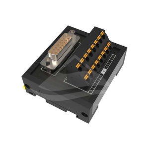

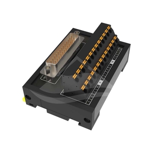
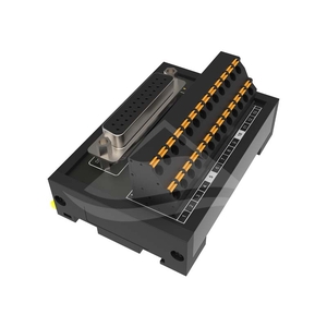

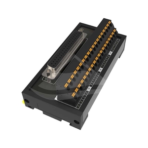
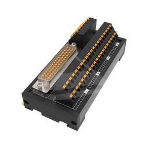
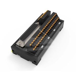
ETD modules provide field-wiring terminals for D-sub signal connections. Each contact count is available with male pins or female sockets. Select the mating connector and module footprint, then match the cable pin assignment to the connected equipment.
| Contacts | Male connector model | Female connector model | Length × width × height |
|---|---|---|---|
| 9 | ETD-09M | ETD-09F | 42mm × 57mm × 41.5mm |
| 15 | ETD-15M | ETD-15F | 65mm × 57mm × 41.5mm |
| 25 | ETD-25M | ETD-25F | 81mm × 55mm × 39mm |
| 37 | ETD-37M | ETD-37F | 111mm × 55mm × 39mm |
| 50 | ETD-50M | ETD-50F | 116mm × 55mm × 39mm |
| Characteristic | All ten models |
|---|---|
| Rated voltage | 24VDC |
| Rated current | 1A |
| Dielectric withstand voltage | 2000VAC minimum; test duration not specified |
| Insulation resistance | >5000MΩ at 500VDC |
| Suitable wire range | 26-16AWG |
| Applicable cable conductor size | 1.5mm² / 16AWG |
| Ambient temperature range | -55°C to +105°C |
The applicable cable conductor size is listed separately from the terminal wire range. Matching contact count and connector gender establishes the mechanical selection; equipment-specific signal assignments must also match.
