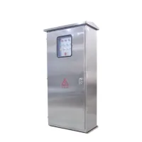
Power distribution and control assembly
These cabinets are intended for industrial and mining installations using 50Hz AC three-phase three-wire or three-phase four-wire systems below 500V. The enclosure accommodates power distribution, lighting distribution, metering and motor-control equipment.
The bent and welded cabinet has a hinged front door opening beyond 90°, an internal mounting plate and cable-wired incoming and outgoing circuits. The illustrated layouts include a top-covered stainless steel cabinet with an observation window and a painted steel control assembly.
Enclosure construction
| Component | Specification |
|---|
| Body material | Cold-rolled steel, SS304 or SS316 |
|---|
| Body thickness | 1.5mm |
|---|
| Front door | 2mm with two reinforcing frames |
|---|
| Mounting plate | 2.5mm |
|---|
| Painted-steel finish | Textured epoxy-polyester powder coating |
|---|
| Customization | Dimensions, material thickness, openings and enclosure layout |
|---|
Control and protection functions
Auxiliary circuits can be configured for local, remote or automatic control. Incoming and feeder switches can use instantaneous and thermal-magnetic trip protection. Incoming-switch instantaneous protection may be omitted where required by the selected protection-coordination arrangement; motorized or manual operation and automatic switching are available. Feeder fault protection is optional.
Motor-control circuits provide short-circuit, overload, undervoltage-release and phase-loss protection. Incoming circuits can include an ammeter and voltmeter. Design references include IEC60439-1:1992 and GB7251.1-1997.
Operating conditions
| Condition | Limit |
|---|
| Installation | Indoors |
|---|
| Ambient temperature | -5°C to +40°C; 24-hour average no higher than +35°C |
|---|
| Altitude | Up to 2000m |
|---|
| Relative humidity | Up to 50% at +40°C; higher humidity at lower temperatures, including 90% at +20°C |
|---|
| Condensation | Occasional condensation can occur with temperature changes |
|---|
| Installation inclination | No more than 5° |
|---|
| Location | Free from severe vibration, shock and conditions that corrode electrical components |
|---|
Fuse-switch combination
| Model | Rated current (A) | Fuse-link ratings (A) |
|---|
| HR3-400/34 | 400 | 150, 200, 250, 300, 350, 400 |
Current transformer
| Model | Primary current options (A) | Secondary current (A) |
|---|
| LM-0.5 | 75, 100, 150, 200, 300, 600 | 5 |
Fuse options
| Model | Fuse-holder rated current (A) | Fuse-link ratings (A) |
|---|
| RL1-15 | 15 | 2, 4, 5, 6, 10, 15 |
| RL1-60 | 60 | 20, 25, 30, 35, 40, 50, 60 |
| RL1-100 | 100 | 30, 40, 50, 60, 80, 100 |
| RL1-200 | 200 | 80, 100, 120, 150, 200 |
| RL1-400 | 400 | 150, 200, 250, 300, 350, 400 |
AC contactors
| Model | Rated current (A) | AC coil voltage options (V) |
|---|
| CJ10-10 | 10 | 110, 220, 380 |
| CJ10-20 | 20 |
| CJ10-40 | 40 |
| CJ10-80 | 80 |
| CJ10-150 | 150 |