


| Part Number: | ULO | - | DSTB | / | 8 | - | 02 | P | - | 1 | 000A |
|---|---|---|---|---|---|---|---|---|---|---|---|
| Explanation: |
Brand |
Terminal Family |
Model Size 8 - DSTB/8; 13mm pitch, 2–14 poles |
Poles 02–14 - DSTB/8 |
Pole Suffix |
Colour 1 - Grey |
Customer Requirements 000A - Standard suffix shown in the DSTB drawings |
DSTB screw terminal blocks provide a single bank of separated power connections with PA66 insulating housings, nickel-plated brass conductors and PC covers. Select the size by current, conductor type, pole count and mounting space. The maximum pole count decreases as the terminal size increases.
| Model | Pitch | Poles | Rated current | Terminal screw | Tightening torque |
|---|---|---|---|---|---|
| DSTB/8 | 13mm | 2–14 | 40A | M5 | 2N·m |
| DSTB/22 | 16mm | 2–10 | 75A | M6 | 5N·m |
| DSTB/38 | 21mm | 2–7 | 100A | ||
| DSTB/80 | 27mm | 2–6 | 180A | M8 | 12N·m |
| Model | UL use group | Rated voltage | Rated current | Dielectric withstand voltage |
|---|---|---|---|---|
| DSTB/8 | B | 600V | 40A | 4000VAC for 1 minute |
| DSTB/22 | 75A | |||
| DSTB/38 | 100A | |||
| DSTB/80 | 180A | 6000VAC for 1 minute |
| Model | IEC rated current | IEC rated voltage | Overvoltage category | Rated impulse voltage |
|---|---|---|---|---|
| DSTB/8 | 40A | 800V | III | 8kV |
| DSTB/22 | 75A | |||
| DSTB/38 | 100A | 320V | 12kV | |
| DSTB/80 | 180A | 630V |
The drawings show a 200A body marking for DSTB/80. Its electrical selection rating is 180A as listed above.
| Model | Flexible conductor | Flexible conductor with ferrule | Solid conductor | UL wire range |
|---|---|---|---|---|
| DSTB/8 | 1.5–8mm² | 1.5–8mm² | 1.5–8mm²; 10mm² solid also specified | 12–8AWG |
| DSTB/22 | 4–22mm² | 4–22mm² | 2.5–22mm² | 22–4AWG |
| DSTB/38 | 4–38mm² | 4–38mm² | 2.5–38mm² | 20–2AWG |
| DSTB/80 | 4–95mm² | 4–95mm² | 4–75mm² | Not specified |
Keep the solid and flexible conductor limits separate. Use the stated terminal screw and torque for the selected model; a mounting fastener is not interchangeable with a conductor-clamping screw.
| Common parameter | Specification |
|---|---|
| Connection method | Screw connection |
| Number of rows | 1 |
| Protection rating | IP20 |
| Operating temperature | -40°C to +105°C |
| Stripping length | Not specified |
| Separate mounting screw and tightening torque | Not specified |
| Component or property | Specification |
|---|---|
| End and centre housings | PA66, UL94V-0 |
| Insulation material group | I |
| Cover | PC |
| Conductor | Nickel-plated brass |
| Terminal screws and nuts | Zinc-plated steel; terminal screw sizes are listed in the model selection table |
| Long screw | M3 zinc-plated steel |
| Additional screw nut, DSTB/22, DSTB/38 and DSTB/80 | Zinc-plated steel |
| Nut housing, DSTB/38 and DSTB/80 | PA66, UL94V-0 |
| Insulating gasket, DSTB/80 | NPR |
Specify the DSTB size, pole count, colour code and customer requirement suffix. Use the individual model's pole range; the full series does not share one maximum pole count.
| Model field | Pole field XXP | Colour field | Customer requirement suffix |
|---|---|---|---|
| DSTB/8 | 02P–14P | 1: Grey; 2: Blue; 3: Black; 4: Green; 5: Orange; 6: Red; 7: Transparent; 8: Yellow; 9: White | 00A standard designation |
| DSTB/22 | 02P–10P | ||
| DSTB/38 | 02P–07P | ||
| DSTB/80 | 02P–06P |
Dimensions are in millimetres. N is the selected pole count and corresponds to P in the drawings. The end views have different local widths; use the dimension line belonging to the relevant end and mounting datum.
| Model | Overall length | Maximum width | Overall height | End-to-first-position offset |
|---|---|---|---|---|
| DSTB/8 | 13×(N−1)+36.10 | 26.00 | 42.00 | 18.05 |
| DSTB/22 | 16×(N−1)+47.00 | 31.80 | 47.00 | 23.50 |
| DSTB/38 | 21×(N−1)+50.00 | 36.80 | 56.00 | 25.00 |
| DSTB/80 | 27×(N−1)+55.10 | 45.70 | 70.00 | 27.55 |


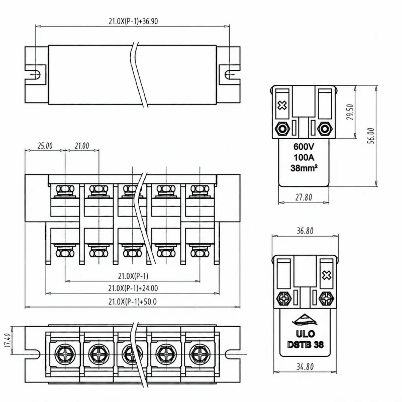

Apply these tolerances where no individual dimensional tolerance is shown.
| Dimension range | Total pitch tolerance | Nominal dimension tolerance |
|---|---|---|
| Over 0mm to 30mm | ±0.18mm | ±0.20mm |
| Over 30mm to 53mm | ±0.20mm | ±0.25mm |
| Over 53mm to 70mm | ±0.25mm | ±0.30mm |
| Over 70mm to 90mm | ±0.30mm | ±0.35mm |
| Over 90mm to 115mm | ±0.35mm | ±0.44mm |
| Over 115mm to 150mm | ±0.44mm | ±0.55mm |
| Over 150mm to 200mm | ±0.55mm | ±0.70mm |
| Over 200mm to 250mm | ±0.70mm | ±0.80mm |
| Over 250mm to 320mm | ±0.75mm | ±0.90mm |
| Geometric characteristic | Applicable dimension | Tolerance |
|---|---|---|
| Perpendicularity | 0–10mm | 0.2mm |
| Over 10mm | 0.3mm | |
| Symmetry | All | 0.3mm |
| Straightness | Over 0mm to 100mm | 0.2mm |
| Parallelism | Over 100mm to 150mm | 0.3mm |
| Over 150mm | 0.5mm |
Four model-specific drawings are attached, covering the electrical values, conductor ranges, component materials, dimensions and ordering fields for DSTB/8, DSTB/22, DSTB/38 and DSTB/80.
