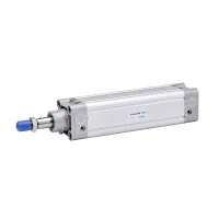
| Part Number: | DNC | 63 | x | 50 | - | PPV | A |
|---|---|---|---|---|---|---|---|
| Explanation: |
Series DNC - Basic cylinder type |
Bore 32 - 32mm |
Stroke 50 - 50mm; all listed bores |
Cushioning Blank - Without cushioning; omit PPV |
Magnet Blank - Standard configuration; omit A |
DNC double-acting pneumatic cylinders use an aluminium-alloy body in an ISO 6431 design format. Specify the bore, stroke, mounting arrangement, cushioning and magnetic-piston option as a complete configuration. The detailed operating specifications below cover bores from 32mm to 100mm; the stroke-selection table also includes 125mm and 160mm bores.
| Code or field | Selection |
|---|---|
| DNC | Basic cylinder type |
| HNC | Axial mounting arrangement |
| FNC | Front or rear flange arrangement |
| SNCB | Double-ear mounting arrangement |
| SNCL | Single-ear mounting arrangement |
| Bore × stroke | Dimensions in millimetres; 63×50 means 63mm bore and 50mm stroke |
| PPV | Pneumatic cushioning |
| Cushion code omitted | Without cushioning |
| A | Magnetic piston |
| Magnetic option omitted | Standard configuration |
DNC63×50-PPVA combines the basic cylinder, 63mm bore, 50mm stroke, pneumatic cushioning and magnetic piston. The magnetic option identifies the piston configuration; it does not specify an included sensor or sensor model.
| Parameter | Specification |
|---|---|
| Action | Double acting |
| Working medium | Air filtered through a 40μm element |
| Operating pressure | 0.1–0.9MPa |
| Proof pressure | 1.35MPa |
| Working temperature | -5–70°C |
| Cushioning | Adjustable air cushion on the PPV configuration |
| Body | Aluminium alloy |
| Bore | Nominal port size | Adjustable cushion stroke |
|---|---|---|
| 32mm | 1/8″ | 24mm |
| 40mm | 1/4″ | |
| 50mm | 1/4″ | |
| 63mm | 3/8″ | |
| 80mm | 3/8″ | 32mm |
| 100mm | 1/2″ |
Cushion stroke describes the end-of-travel cushioning distance, not the cylinder's working stroke. Proof pressure is a separate test limit and is not the continuous operating rating.
All entries in the following table are in millimetres. Listed standard strokes, maximum standard stroke and maximum stroke are separate selection fields. Specify the required stroke and mounting arrangement together, particularly for extended strokes.
| Bore | Listed standard strokes | Maximum standard stroke | Maximum stroke |
|---|---|---|---|
| 32 | 25, 50, 75, 100, 125, 150, 175, 200, 250, 300, 350, 400, 500 | 1000 | 2000 |
| 40 | 25, 50, 75, 100, 125, 150, 175, 200, 250, 300, 350, 400, 500, 600, 700, 800 | 1200 | 2000 |
| 50 | 25, 50, 75, 100, 125, 150, 175, 200, 250, 300, 350, 400, 500, 600, 700, 800, 900, 1000 | 1200 | 2000 |
| 63 | 25, 50, 75, 100, 125, 150, 175, 200, 250, 300, 350, 400, 500, 600, 700, 800, 900, 1000 | 1500 | 2000 |
| 80 | 25, 50, 75, 100, 125, 150, 175, 200, 250, 300, 350, 400, 500, 600, 700, 800, 900, 1000 | 1500 | 2000 |
| 100 | 25, 50, 75, 100, 125, 150, 175, 200, 250, 300, 350, 400, 500, 600, 700, 800, 900, 1000 | 1500 | 2000 |
| 125 | 25, 50, 75, 100, 125, 150, 175, 200, 250, 300, 350, 400, 500, 600, 700, 800, 900, 1000 | 1500 | 2000 |
| 160 | 25, 50, 75, 100, 125, 150, 175, 200, 250, 300, 350, 400, 500, 600, 700, 800, 900, 1000 | 1500 | 2000 |
Port sizes, cushion distances and the detailed operating specification for the 125mm and 160mm bores are not defined in the 32–100mm specification table. Select those larger configurations with their corresponding technical details.
