
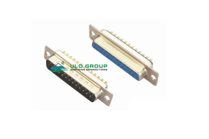
| Part Number: | ULO | - | MP421K | - | 09 | M | B | T | 8 | S | S |
|---|---|---|---|---|---|---|---|---|---|---|---|
| Explanation: |
Brand ULO - ULO |
Model DB421 - D-sub solder-cup connector |
Contacts 09 - 9 contacts |
Connector Type M - Male |
Colour B - Black |
Shell Plating T - Front and back shells tin plated |
Contact Plating Si - Selective gold flash; DB421 only |
Screw Type S - Standard without nut; both models |
Screw Dimension A S - Standard without nut |
ULO-DB421 and ULO-MP421K are standard-density D-sub connectors for soldered wire termination. Both offer male and female versions with 9, 15, 25, 37 or 50 contacts. MP421K uses machined contacts and has its own current rating and contact-finish options.
| Characteristic | DB421 | MP421K |
|---|---|---|
| Contact construction | Solder-cup D-sub contacts | Machined solder-cup contacts |
| Rated current | Unspecified | 1A |
| Temperature range | -45°C to +105°C | -45°C to +110°C |
| Insulator | PBT with 30% glass fibre | Glass-fibre-filled thermoplastic |
| Screw structures | Standard without nut, CC, CS or CSH | Standard without nut, CC or CS |
Select the exact model before specifying contact finish or hardware. These connectors use two contact rows at 9–37 positions and a separate three-row arrangement at 50 positions.
| Characteristic | DB421 and MP421K |
|---|---|
| Insulation resistance | ≥1000MΩ |
| Contact impedance | ≤20mΩ |
| Dielectric withstand test | 500VAC for 1 minute |
| Insulation material group | I |
| Material flammability grade | UL94V-0 |
| Contact material | Copper alloy |
| Shell material | Steel |
The 500VAC value describes a dielectric test; rated working voltage and solder-wire gauge are unspecified.
| Field | DB421 | MP421K |
|---|---|---|
| Contact count | 09: 9; 15: 15; 25: 25; 37: 37; 50: 50 | 09: 9; 15: 15; 25: 25; 37: 37; 50: 50 |
| Connector type | M: male; F: female | M: male; F: female |
| Insulator colour | B: black; W: white; U: blue | B: black; W: white; U: blue |
| Shell plating | T: front and back tin; N: front nickel, back tin | T: front and back tin; N: front nickel, back tin |
| Contact plating | Full gold flash: code unspecified; Si: selective gold flash; 6: full tin | 8: full gold flash; G: full 3µin gold; J: full 5µin gold |
| Screw type | S: standard without nut; 1: CC; 2: CS; 3: CSH | S: standard without nut; 1: CC; 2: CS |
| Screw-dimension code | Dimension A or configuration |
|---|---|
| S | Standard without nut |
| 1 | 5.00mm |
| 2 | 3.00mm |
| 3 | 5.20mm |
| 4 | 4.80mm |
| 5 | 5.80mm |
| 6 | 4.00mm |
Screw dimension A belongs to the hardware side views and is separate from mating-outline dimension A in the connector tables. Thread designation is unspecified.


Both models use the following dimensions for 9, 15, 25 and 37 contacts. A describes the male mating outline, D the female mating outline, B the mounting-centre distance and C the overall flange length. All table dimensions are in millimetres.
| Contacts | A ±0.2 | B ±0.2 | C ±0.3 | D |
|---|---|---|---|---|
| 9 | 17.90 | 24.99 | 30.80 | 16.33 |
| 15 | 26.50 | 33.32 | 39.14 | 24.66 |
| 25 | 40.00 | 47.04 | 53.04 | 38.38 |
| 37 | 56.50 | 63.50 | 69.32 | 54.84 |
The two-row profiles show 2.77mm contact pitch and 2.84mm row spacing. The flange height is 12.50mm; male and female mating-height references are 9.20mm and 7.90mm respectively. Side profiles show a 0.90mm flange reference, with 10.70mm female and 11.00mm male longitudinal references.
| Feature | 50-contact female | 50-contact male |
|---|---|---|
| Overall flange length | 67.04mm | 67.04mm |
| Mounting centres | 61.00mm | 61.00mm |
| Mating-outline width | 52.34mm | 54.30mm |
| Mating-outline height | 10.80mm | 12.20mm |
| Overall flange height | 15.30mm | 15.30mm |
| Outer contact-row span | 5.68mm | 5.68mm |
| Horizontal contact pitch | 2.77mm | 2.77mm |
| Stagger offset | 1.385mm | 1.385mm |
| Mounting holes | 2 × Ø3.05mm | 2 × Ø3.05mm |
Use the separate 50-contact profiles when checking the larger flange. DB421 includes a CSH hardware view with 4.80mm and 11.80mm references; both models provide standard, CC and CS views for interpreting the screw-dimension field.


