





| Part Number: | CZ-8 | 104 | |
|---|---|---|---|
| Explanation: |
Series CZ-8 - Vertical limit switch series |
Actuator 104 - Plastic roller lever |
Cable entry Blank - Rubber tail sleeve; no suffix is added |
CZ-8 limit switches use a metal body, reinforced plastic cover and rubber cable sleeve with snap-action 1NO+1NC contacts. The actuator range includes fixed and adjustable roller levers, an adjustable rod, plain and roller plungers, and flexible spring heads. Choose the model by approach direction, available movement and operating force, then use its own outline drawing for installation.
The normally open circuit is 13-14 and the normally closed circuit is 11-12. Only the NC contact on the six lever versions identified below has the specified direct-opening function.
| Model | Head code | Actuator | NC direct opening |
|---|---|---|---|
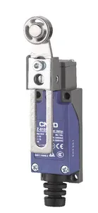
| CZ-8104 | 104 | Plastic roller lever | Yes |
| CZ-8105 | 105 | Metal roller lever | |
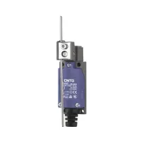
| CZ-8107 | 107 | Adjustable rod lever | |
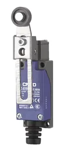
| CZ-8108 | 108 | Adjustable lever with plastic roller | |
| CZ-8109 | 109 | Adjustable lever with metal roller | |
| CZ-8111 | 111 | Plunger | Not specified |
| CZ-8111M | 111M | Plunger with metal head | |
| CZ-8112 | 112 | Cross-wheel roller plunger | |
| CZ-8112M | 112M | Cross-wheel roller plunger with metal head | |
| CZ-8122 | 122 | Vertical-wheel roller plunger | |
| CZ-8122M | 122M | Vertical-wheel roller plunger with metal head | |
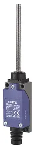
| CZ-8166 | 166 | Plastic rod with coil spring | |
| CZ-8167 | 167 | Coil spring | |
| CZ-8168 | 168 | Metal rod with coil spring | |
| CZ-8169 | 169 | Flexible whisker | |
| CZ-8108H | 108H | Adjustable lever with rubber roller | Yes |
A complete code joins the fixed series identifier CZ-8 to the selected head code. The rubber tail sleeve has no suffix, so CZ-8104 is a complete model. Keep compound actuator codes such as 111M and 108H intact.
| Parameter | Value and condition |
|---|---|
| Contact form | 1NO+1NC, snap action |
| Cable entry | Rubber tail sleeve |
| Operating speed | 5mm/s-0.5m/s |
| Electrical operating frequency | 30 operations/min |
| Initial contact resistance | 25mΩ maximum |
| Insulation resistance | 100MΩ minimum at 500VDC |
| Minimum applicable load | 24VDC, 10mA |
| Rated insulation voltage Ui | 300V |
| Rated impulse withstand voltage Uimp | 4kV |
| Conventional free-air thermal current Ith | 10A |
| Dielectric strength between open contacts of the same polarity | 1000VAC, 50/60Hz, for 1 minute |
| Dielectric strength between live and non-live metal parts | 1500VAC, 50/60Hz, for 1 minute |
| Dielectric strength between each terminal and ground | |
| Vibration resistance | 10-55Hz, 1.5mm double amplitude |
| Shock resistance, mechanical durability | 1000m/s², approximately 100g |
| Shock resistance, malfunction | 300m/s², approximately 30g; coil-spring types excluded |
| Operating temperature | -20°C to +70°C, without icing |
| Relative humidity | Below 95%RH |
| Enclosure protection | IP65 |
| Electrical endurance | Load condition |
|---|---|
| More than 500,000 cycles | 240VAC, 3A, resistive |
| More than 300,000 cycles | 240VAC, 6A, resistive |
| More than 500,000 cycles | 250V, 6A, resistive |
Endurance figures apply to their stated loads. Select switching current by voltage, contact and load type; the 10A thermal-current value is not a universal switching rating.
All currents in the following table are in amperes. A dash indicates that no rating is specified.
| Rated voltage | Noninductive load | Inductive load | ||||||
|---|---|---|---|---|---|---|---|---|
| Resistive | Lamp | Inductive | Motor | |||||
| NC | NO | NC | NO | NC | NO | NC | NO | |
| 125VAC | 6 | 1.5 | 0.7 | 3 | 2 | 1 | ||
| 250VAC | 1 | 0.5 | 1.5 | 0.8 | ||||
| 12VDC | 6 | 3 | 4 | 3 | ||||
| 24VDC | ||||||||
| 125VDC | 0.4 | 0.2 | — | — | — | |||
| 50VDC | ||||||||
| Contact | Maximum surge current |
|---|---|
| NC | 24A |
| NO | 12A |
These are steady-current ratings. The inductive-load condition is power factor 0.4 for AC or time constant below 7ms for DC. Lamp loads assume inrush up to ten times steady current; motor loads assume up to six times steady current.
OF is maximum operating force; RF is minimum release force. PT is maximum pretravel unless a tolerance is shown. OT and TT are minimum overtravel and total travel. MD is maximum differential travel unless a tolerance is shown. OP is the operating position relative to the drawing datum. Dashes denote unspecified values.
| Lever model | OF | RF | PT | OT | MD | TT | OP |
|---|---|---|---|---|---|---|---|
| CZ-8104 | 7.5N | 1N | 20° | 75° | 12° | 95° | — |
| CZ-8105 | |||||||
| CZ-8107 | |||||||
| CZ-8108 | |||||||
| CZ-8109 | |||||||
| CZ-8108H |
| Plunger model | OF | RF | PT | OT | MD | TT | OP |
|---|---|---|---|---|---|---|---|
| CZ-8111 | 9N | 1N | 1.8mm | 4mm | 1mm | 5.5mm | 26±0.8mm |
| CZ-8111M | 1.5N | ||||||
| CZ-8112 | 37±0.8mm | ||||||
| CZ-8112M | |||||||
| CZ-8122 | |||||||
| CZ-8122M |
| Flexible actuator model | OF | RF | Angular PT | OT | Angular MD | TT | OP |
|---|---|---|---|---|---|---|---|
| CZ-8166 | 1.5N | — | 15±5° | — | — | — | — |
| CZ-8167 | |||||||
| CZ-8168 | 10±2° | ||||||
| CZ-8169 |
Operate spring and whisker actuators horizontally within the outer third of their length, measured from the tip. Avoid loading the root or pressing beyond the specified movement; rebound can cause additional contact operations.
| Model | Dimensional features |
|---|---|
| CZ-8104 / CZ-8105 | Ø18×6.3mm roller; R30mm lever; 125.3mm illustrated overall height |
| CZ-8107 | Ø2.6×128mm rod; 30-100mm setting range |
| CZ-8108 / CZ-8109 | Ø18×6.5mm roller; R29.5-R72.5mm adjustment; 123.5-166.5mm overall height |
| CZ-8111 / CZ-8111M | Ø8.7mm plunger; 102.5mm overall height |
| CZ-8112 / CZ-8112M / CZ-8122M | Ø12.6×3.8mm roller; 114mm overall height |
| CZ-8122 | Ø12.6×3.8mm vertical roller; 112mm overall height |
| CZ-8166 / CZ-8167 | 173mm overall height; plastic-rod spring and exposed coil respectively |
| CZ-8168 | Metal-rod spring; 174.5mm overall height |
| CZ-8169 | Flexible whisker; 173.5mm overall height |
| CZ-8108H | Ø50×8mm rubber roller; R40-R80mm adjustment; 150.4mm illustrated height |
For CZ-8104, CZ-8105, CZ-8107, CZ-8108, CZ-8109 and CZ-8108H, the lever can be set around 360° after loosening its hexagonal nut. The head can be installed in four orientations at 90° intervals. Retighten the relevant screws evenly to the specified torque and keep foreign material out of the housing.
For CZ-8112 and CZ-8122 roller plungers, use an operating cam angle below 30°. Refer to the attached drawings for the cam, sleeve-top and groove relationship, including the 2.8mm illustrated offset. Protect the actuator from drops and impact.
Isolate power before wiring. Remove the cover, pass the cable through the rubber sleeve, fit insulated crimp terminals and tighten the terminal screws. Keep wire fragments out of the switch. Refit the sleeve in its cover groove and tighten the three cover screws evenly to 0.49-0.59N·m. Route the cable so that the cover closes freely without trapping terminals.
| Cable type | Recommended cable characteristics | ||
|---|---|---|---|
| Cores | Conductor | Overall diameter | |
| Plastic/rubber-insulated flexible cable | 2, 3 or 4 | 0.5-0.75mm² | Round, Ø6-9mm |
| 600V plastic-insulated, plastic-sheathed cable (VVF) | 2 | Ø1mm, Ø1.2mm or Ø1.6mm | |
The flexible-wire connection range is AWG20-AWG18 or 0.5-0.75mm². Use insulated M3.5-compatible crimp terminals no more than 0.5mm thick, positioned clear of the casing. Keep silicone oil away from the contacts and cable system.
| Crimp-terminal dimension | Value |
|---|---|
| Thickness t | 0.5mm maximum |
| Hole diameter Ødz | 3.7mm |
| Barrel diameter ØD | 2.9mm |
| Width B | 6.6mm |
| Overall length L | 19mm |
| Dimension F | 7.7mm |
| Dimension I | 8mm |
Secure the cable approximately 50mm from the switch base and maintain a bend radius of at least 45mm. Keep the rubber sleeve straight. Mount the switch so that water cannot run along the cable into the enclosure; reverse installation with the cable entry uppermost is not recommended.
| Mounting method | Panel holes | Hole spacing | Fastener arrangement |
|---|---|---|---|
| Front mounting through panel | 4×Ø4.5mm | 21±0.3mm × 56±0.3mm | M4 bolts, nuts and washers |
| Front mounting into threaded panel | 4×M4, 0.7mm pitch | 21±0.2mm × 56±0.2mm | M4 bolts and washers |
| Rear mounting | 4×Ø5.5mm | 21±0.3mm × 56±0.3mm | M5 fastening arrangement; see rear-mount drawing |
The body's M5 threads have a 0.8mm pitch and at least 7.5mm thread depth. For rear mounting, screw length must not exceed panel thickness plus 7mm. The body mounting holes and the panel clearance holes have different specified diameters.
| Figure reference | Fastener | Tightening torque |
|---|---|---|
| 1 | Head mounting screws | 0.19-0.29N·m |
| 2 | Housing cover screws | 0.49-0.59N·m |
| 3 | Lever installation screw | 2.45-2.94N·m |
| 4 | M3 terminal screw | 0.49-0.59N·m |
| 5 | M4 body mounting screw with hexagonal nut | 2.45-2.94N·m |
| 6 | M5 rear body mounting screw with hexagonal nut | 4.90-5.88N·m |
| Designation | Referenced standard | Documentation |
|---|---|---|
| CCC | GB/T 14048.5 | Request applicable model documentation for the intended market |
| TUV | EN 60947-5-1 | |
| CE |
| Utilization category | Operational rating |
|---|---|
| AC-15 | 6A at 250VAC |
| DC-13 | 0.3A at 220VDC |
For loads below 24VDC/10mA, select a specifically configured low-load contact version. Contacts previously used for general loads should not be reassigned to small loads. Suitable suppression and contact-protection circuits help limit noise from contact bounce and damage from impulse currents.
These are general industrial switches. Personnel-protection duties, nuclear or utility infrastructure, outdoor or chemically aggressive conditions, strong electromagnetic disturbance, fire or explosion hazards, military equipment and aerospace require a separately specified design and written application approval.
