


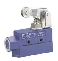


| Part Number: | CZ-6 | 101 | - | P |
|---|---|---|---|---|
| Explanation: |
Series CZ-6 - Cast aluminum horizontal limit switch family |
Actuator 001 - Flat-head plunger |
Conduit NONE - M20 single conduit entry; omit the suffix and preceding separator |
CZ-6 horizontal limit switches enclose a CM-1 switching mechanism in a cast aluminum housing. Plunger, roller, bracket-lever and full-spring heads provide different operating forces and travel. All use a snap-action changeover contact with COM, NC and NO connections. Select the head and sealing arrangement by model before choosing the mounting position and cam profile.
The code combines CZ-6 with a three-digit actuator designation. The standard single conduit entry is M20 and has no suffix; add -P for PG13.5. For example, CZ-6101-P selects the sealed flat-head plunger with a PG13.5 entry.
| Model | Actuator code | Head | IP65 specified | OF max. | RF min. | PT max. | OT min. | MD max. | OP |
|---|---|---|---|---|---|---|---|---|---|
| CZ-6001 | 001 | Flat-head plunger | No | 3.5N | 1.14N | 0.4mm | 5.5mm | 0.05mm | 38.2±0.8mm |
| CZ-6002 | 002 | Transverse roller plunger | 0.5mm | 3.6mm | 49.7±1mm | ||||
| CZ-6003 | 003 | Vertical roller plunger | |||||||
| CZ-6004 | 004 | V-bracket roller lever | 5.7N | 1.7N | 4mm | 6mm | 0.4mm | — | |
| CZ-6101 | 101 | Flat-head plunger with sealing ring | Yes | 8N | 2.4N | 2mm | 5mm | 0.1mm | 45.8±0.8mm |
| CZ-6102 | 102 | Transverse roller plunger with sealing ring | 5N | 1N | 1mm | 3.5mm | 0.12mm | 49.7±0.8mm | |
| CZ-6103 | 103 | Vertical roller plunger with sealing ring | |||||||
| CZ-6104 | 104 | V-bracket roller lever with sealing ring | 6.4N | 2.3N | 5mm | 6mm | 0.4mm | — | |
| CZ-6143 | 143 | Z-bracket roller lever |
| Model | Actuator code | Head | Protection | OF max. | Angular PT | Operating zone |
|---|---|---|---|---|---|---|
| CZ-6106 | 106 | Full spring head with sealing ring | IP65 | 1.5N | 15±5° | Within the upper one-third of actuator length, measured from the tip |
OF is operating force, RF release force, PT pretravel, OT overtravel, MD movement differential and OP operating position. A dash means unspecified. RF, MD, OT and OP are not specified for the spring head. IP65 applies only to CZ-6101, CZ-6102, CZ-6103, CZ-6104, CZ-6143 and CZ-6106; it is not a family-wide rating.
| Parameter | Value and condition |
|---|---|
| Operating speed | 5mm/s–0.5m/s |
| Electrical operating frequency | 20 operations/min |
| Initial contact resistance | 25mΩ maximum |
| Insulation resistance | 100MΩ minimum at 500VDC |
| Minimum applicable load | 24VDC,10mA |
| Rated insulation voltage Ui | 380V |
| Impulse withstand voltage Uimp | 2.5kV |
| Conventional free-air thermal current Ith | 15A |
| Dielectric strength: open terminals of the same polarity | 1000VAC,50/60Hz,1 minute |
| Dielectric strength: live parts to non-current-carrying metal | 1890VAC,50/60Hz,1 minute |
| Dielectric strength: each terminal to ground | |
| Vibration | 10–55Hz,1.5mm double amplitude |
| Shock, mechanical durability | 1000m/s² |
| Shock, malfunction resistance | 100m/s²; excludes the coil-spring model CZ-6106 |
| Ambient temperature | -20°C to +80°C, without icing |
| Humidity | 95%RH maximum |
| Electrical life:240VAC/3A resistive | More than 500000 cycles |
| Electrical life:240VAC/15A resistive | More than 200000 cycles |
| Electrical life:250VAC/15A resistive | More than 500000 cycles |
Life values retain their individual test conditions. Thermal current and utilization-category ratings are separate from the load-specific switching limits below.
| Voltage | Noninductive load | Inductive load | ||||||
|---|---|---|---|---|---|---|---|---|
| Resistive | Lamp | Inductive | Motor | |||||
| NC | NO | NC | NO | NC | NO | NC | NO | |
| 125VAC | 5A | 1.5A | 0.7A | 3A | 2A | 1A | ||
| 250VAC | 1A | 0.5A | 1.5A | 0.8A | ||||
| 8VDC | 3A | 5A | 4A | 3A | ||||
| 14VDC | 4A | |||||||
| 30VDC | ||||||||
| 125VDC | 0.4A | — | — | — | ||||
| 250VDC | 0.2A | |||||||
| Contact | Maximum inrush current |
|---|---|
| NC | 24A |
| NO | 12A |
Blank load-table entries are shown as dashes and do not establish a rating. Inductive-load conditions are AC power factor 0.4 minimum and DC time constant 7ms maximum. Lamp inrush is 10 times steady current; motor inrush is 6 times steady current. Check these load conditions together with the NC/NO inrush limits.

| Utilization category | Operational voltage | Operational current |
|---|---|---|
| AC-15 | 250VAC | 15A |
| DC-13 | 220VDC | 0.3A |
| Marking/specification | Referenced standard |
|---|---|
| CCC | GB/T14048.5 |
| CE | EN60947-5-1 |
| TÜV specification |
Confirm conformity documentation for the selected model and destination when an approval is required. The AC-15 figure does not replace the 5A general resistive-load entries.
The standard drawings show an M20 conduit entry and two M4×45 mounting screws. The body is 25.4±0.3mm wide with mounting centers of 25.4±0.12mm. Most models have an 86mm overall body length; CZ-6106 is 85.5mm. For the installation plate, use two Ø4.3mm clearance holes or M4 tapped holes on 25.4±0.1mm centers. Refer to the individual drawing for all height and operating-position datums.
| Model | Actuator dimensions |
|---|---|
| CZ-6001/CZ-6101 | Flat plunger contact surface R12 |
| CZ-6002/CZ-6003/CZ-6102/CZ-6103 | Ø12.7×4.8mm roller; transverse or vertical orientation follows the model |
| CZ-6004/CZ-6104 | Ø19.1×7.9mm roller;39.7mm arm dimension and23.1mm roller offset |
| CZ-6143 | Ø18.7×9mm roller;39.7mm arm dimension and17.4mm offset radius |
| CZ-6106 | Ø6.5mm spring head;150±2.5mm dimension from the indicated mounting datum;9.5mm side offset |
| Fastener | Tightening torque |
|---|---|
| Cover mounting screws | 1.18–1.37N·m |
| M4 side mounting screws | |
| M3.5 terminal screws | 0.78–1.18N·m |
| Roller-arm mounting nut | 4.90–5.88N·m |
Set the roller-arm position and retighten its nut before operation. Fit each O-ring correctly at the side mounting screws to maintain sealing. Keep chips and other debris out of the conduit entry and use a smooth cam with sufficient travel margin. Set actual working overtravel to 70–100% of the stated OT.
| Conductor type | Cores | Conductor size | Finished cable OD |
|---|---|---|---|
| Flexible insulated wire | 2 | 0.5–0.75mm² | Circular,Ø6–9mm |
| 3 | |||
| 4 | |||
| 600V plastic-insulated, plastic-sheathed VVF cable | 2 | Ø1mm/Ø1.2mm/Ø1.6mm conductor |
For insulated M3.5 crimp connections, use 0.5–0.75mm² conductors (AWG20–18), with terminal thickness no greater than 0.5mm. The terminal sketch specifies a Ø3.7mm screw hole, Ø2.9mm barrel, 6.6mm width, 19mm overall length and 7.7mm/8mm section lengths. Place terminals clear of the housing and route wires so the cover closes without force.
Disconnect power before installation, wiring or maintenance. Protect the actuator from cutting chips and accumulated dirt. Evaluate sealing-material compatibility where cutting oils, solvents or other chemicals are present, and inspect seals under actual service conditions. Avoid persistent vibration, impacts, resonance and silicone contamination that can degrade the contacts.
For signals below 24VDC/10mA, select a contact design intended for small loads. Contacts previously used for general loads should not be reused for small-signal switching. Apply suitable contact protection for inductive or high-inrush circuits. Personnel-safety, explosive-atmosphere and other unusually demanding applications require separate application approval.
