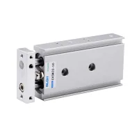
| Part Number: | CXSM | 20 | - | 50 | S |
|---|---|---|---|---|---|
| Explanation: |
Series CXSM - Double-acting twin-rod guided cylinder. |
Bore 6 - 6mm; listed strokes 10, 20, 30, 40 or 50mm |
Stroke 10 - 10mm; all listed bores |
Magnet Blank - Without magnet; omit the suffix |
CXSM double-acting cylinders combine two parallel piston rods with a common front plate. Select the bore, stroke and magnetic option for the mounting space and sensing arrangement. Rubber buffers are fitted at both ends, with 0–5mm stroke adjustment.
CXSM20×40 identifies a 20mm bore and 40mm stroke. Add S for a magnet-equipped version; a blank suffix indicates no magnet.
| Bore | 6mm | 10mm | 15mm | 20mm | 25mm | 32mm |
|---|---|---|---|---|---|---|
| Minimum operating pressure | 0.15MPa | 0.1MPa | 0.05MPa | |||
| Maximum operating pressure | 0.7MPa | |||||
| Port size | M5×0.8 | 1/8in | ||||
| Working fluid | Air filtered through a 40µm filter element | |||||
| Action | Double acting | |||||
| Buffer | Rubber at both ends | |||||
| Stroke adjustment | 0–5mm | |||||
| Ambient temperature | -10–60°C; no freezing | |||||
| Body | Aluminum alloy | |||||
Dimensions below are in mm unless a thread is specified. Use the 6mm-bore outline for CXSM6 and the lower drawing for 10–32mm bores.

| Model | Stroke | 10+stroke/2 | 13+stroke | 45+stroke | 58.5+stroke |
|---|---|---|---|---|---|
| CXSM6-10 | 10 | 15 | 23 | 55 | 68.5 |
| CXSM6-20 | 20 | 20 | 33 | 65 | 78.5 |
| CXSM6-30 | 30 | 25 | 43 | 75 | 88.5 |
| CXSM6-40 | 40 | 30 | 53 | 85 | 98.5 |
| CXSM6-50 | 50 | 35 | 63 | 95 | 108.5 |
| Bore | A | B | C | D | E | G | H | I | J | K | L | NN | O | P |
|---|---|---|---|---|---|---|---|---|---|---|---|---|---|---|
| 10 | 46 | 17 | 44 | 15 | 7.5 | 35 | 20 | 4 | 8 | 9 | 20 | Ø6 | 5 | 3.6 |
| 15 | 58 | 20 | 56 | 18 | 9 | 45 | 25 | 5 | 10 | 30 | Ø8 | 6 | 48 | |
| 20 | 64 | 25 | 62 | 23 | 11.5 | 50 | 28 | 6 | 12 | 12 | Ø10 | 8 | 53 | |
| 25 | 80 | 30 | 78 | 28 | 14 | 60 | 35 | Ø12 | 10 | 64 | ||||
| 32 | 98 | 38 | 96 | 36 | 18 | 75 | 44 | 8 | 16 | 14 | Ø16 | 13 | 76 |
| Bore | Q | R | RR | T | TT | U | |
|---|---|---|---|---|---|---|---|
| 10 | 8.5 | 7 | 30 | 7 | 8 | 5 | 8 |
| 15 | 10 | 10 | 38.5 | 10 | 10 | ||
| 20 | 7.75 | 12.5 | 45 | 7.75 | 9.5 | 6.5 | |
| 25 | 8.5 | 15 | 46 | 15 | 13 | 9 | 9 |
| 32 | 9 | 19 | 56 | 19 | 20 | 11.5 | 10 |
Callouts follow the outline drawing. Thread depths and screw lengths are in mm.
| Bore | F | M | N | OO screw | PP nut |
|---|---|---|---|---|---|
| 10 | 2-M4×0.7 through | 2-Ø3.4 through; 2-Ø6.5 counterbore, depth 3.3 | 2-M3×0.5, depth 5 | M4×0.7×14.5L | M4×0.7 |
| 15 | 2-M5×0.8 through | 2-Ø4.6 through; 2-Ø6.8 counterbore, depth 4.4 | 2-M4×0.7, depth 6 | M4×1.0 | |
| 20 | 2-Ø5.5 through; 2-Ø9.5 counterbore, depth 5.3 | M6×1.0×18.5L | M6×1.0 | ||
| 25 | 2-M6×1.0 through | 2-Ø8.9 through; 2-Ø11 counterbore, depth 6.3 | 2-M5×0.8, depth 7.5 | M8×1.0×18.5L | |
| 32 | 2-M5×0.8, depth 8 | M8×1.25×18.5L | M8×1.25 |
| Bore | UU air ports | V | W | X | Y |
|---|---|---|---|---|---|
| 10 | 4-M5×0.8, depth 4.5; both sides | 4-M3×0.5, depth 4.5; both sides | 2-M4×0.7, depth 7 | M3×0.5×10L | M3×0.5×5L |
| 15 | 4-M4×0.7, depth 5; both sides | 2-M5×0.8, depth 8 | M5×0.8×10L | M5×0.7×4L | |
| 20 | 8-M4×0.7, depth 6; both sides | 2-M6×1.0, depth 10 | M6×1.0×12L | M6×0.8×5L | |
| 25 | 4-1/8in, depth 6.5; both sides | 8-M5×0.8, depth 7.5; both sides | 2-M8×1.25, depth 12 | M8×1.0×14L | M8×1.25×8L |
| 32 | M8×1.25×16L | M8×1.25×16L |
| Model | S | SS | Z | ZZ |
|---|---|---|---|---|
| CXSM10-10 | 10 | 65 | 30 | 82 |
| CXSM10-20 | 20 | 75 | 92 | |
| CXSM10-30 | 30 | 85 | 102 | |
| CXSM10-40 | 40 | 95 | 40 | 112 |
| CXSM10-50 | 50 | 105 | 122 | |
| CXSM15-10 | 10 | 70 | 25 | 89 |
| CXSM15-20 | 20 | 80 | 99 | |
| CXSM15-30 | 30 | 90 | 35 | 109 |
| CXSM15-40 | 40 | 100 | 119 | |
| CXSM15-50 | 50 | 110 | 129 | |
| CXSM20-10 | 10 | 80 | 30 | 104 |
| CXSM20-20 | 20 | 90 | 114 | |
| CXSM20-30 | 30 | 100 | 40 | 124 |
| CXSM20-40 | 40 | 110 | 134 | |
| CXSM20-50 | 50 | 120 | 144 | |
| CXSM20-75 | 75 | 145 | 60 | 169 |
| CXSM20-100 | 100 | 170 | 194 | |
| CXSM25-10 | 10 | 82 | 30 | 106 |
| CXSM25-20 | 20 | 92 | 116 | |
| CXSM25-30 | 30 | 102 | 40 | 126 |
| CXSM25-40 | 40 | 112 | 136 | |
| CXSM25-50 | 50 | 122 | 146 | |
| CXSM25-75 | 75 | 147 | 60 | 171 |
| CXSM25-100 | 100 | 172 | 196 | |
| CXSM32-10 | 10 | 92 | 40 | 122 |
| CXSM32-20 | 20 | 102 | 132 | |
| CXSM32-30 | 30 | 112 | 50 | 142 |
| CXSM32-40 | 40 | 122 | 152 | |
| CXSM32-50 | 50 | 132 | 162 | |
| CXSM32-75 | 75 | 157 | 70 | 187 |
| CXSM32-100 | 100 | 182 | 212 |

