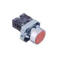


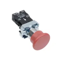


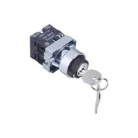


| Part Number: | CXB2 | E | - | B | W3 | 4 | B | 2 |
|---|---|---|---|---|---|---|---|---|
| Explanation: |
Series CXB2 - 22mm modular panel control switch series |
Sealing Variant Blank - IP65 sealing variant in the ordering guide; omit this code |
Operator Material B - Metal operator construction |
Operator and Action A - Momentary flat |
Color or Printed Legend 1 - White |
Lamp Supply Blank - Nonilluminated operator; omit this code |
Contacts 1 - 1NO |
CNTD CXB2 metal control operators fit 22mm panel holes and use flat-pressed, slow-action contacts. The modular head, intermediate holder and contact assembly supports momentary and maintained pushbuttons, mushroom heads, emergency-stop operators, selectors, key operators and twin buttons. Select the complete model, lamp supply and sealing configuration for the control panel.

The compatible example CXB2E-BW34B2 identifies the IP40 variant, metal construction, an illuminated momentary flat operator, red face, 24VAC/DC lamp and 1NC contact. The sealing code is E for IP40 or omitted for the guide's IP65 variant. Specify the supplied sealing arrangement; IP65 is available as a configured option. Preset black selectors and red/green twin operators omit the separate color field. Nonilluminated operators omit the lamp code.
The listed red versions have a normally closed contact; the other colors below have a normally open contact. Use the complete model rather than changing a color digit while retaining an incompatible contact code.
| Operation | White / 1NO | Black / 1NO | Green / 1NO | Red / 1NC | Yellow / 1NO | Blue / 1NO |
|---|---|---|---|---|---|---|
| Flat momentary | CXB2-BA11 | CXB2-BA21 | CXB2-BA31 | CXB2-BA42 | CXB2-BA51 | CXB2-BA61 |
| Flat maintained | CXB2-BAZ11 | CXB2-BAZ21 | CXB2-BAZ31 | CXB2-BAZ42 | CXB2-BAZ51 | CXB2-BAZ61 |
| Raised momentary | CXB2-BL11 | CXB2-BL21 | CXB2-BL31 | CXB2-BL42 | CXB2-BL51 | CXB2-BL61 |
| Raised maintained | CXB2-BLZ11 | CXB2-BLZ21 | CXB2-BLZ31 | CXB2-BLZ42 | CXB2-BLZ51 | CXB2-BLZ61 |
| 40mm mushroom momentary | CXB2-BC11 | CXB2-BC21 | CXB2-BC31 | CXB2-BC42 | CXB2-BC51 | CXB2-BC61 |
| 40mm mushroom maintained | CXB2-BCZ11 | CXB2-BCZ21 | CXB2-BCZ31 | CXB2-BCZ42 | CXB2-BCZ51 | CXB2-BCZ61 |
| 40mm mushroom push-pull | CXB2-BT11 | CXB2-BT21 | CXB2-BT31 | CXB2-BT42 | CXB2-BT51 | CXB2-BT61 |
| 60mm mushroom momentary | CXB2-BR11 | CXB2-BR21 | CXB2-BR31 | CXB2-BR42 | CXB2-BR51 | CXB2-BR61 |
| 60mm mushroom maintained | CXB2-BRZ11 | CXB2-BRZ21 | CXB2-BRZ31 | CXB2-BRZ42 | CXB2-BRZ51 | CXB2-BRZ61 |
○ is the lamp-voltage code and must be replaced before ordering. Black is not listed for illuminated faces. W3 denotes momentary action and WZ3 denotes maintained action.
| Action | White / 1NO | Green / 1NO | Red / 1NC | Yellow / 1NO | Blue / 1NO |
|---|---|---|---|---|---|
| Momentary | CXB2-BW31○1 | CXB2-BW33○1 | CXB2-BW34○2 | CXB2-BW35○1 | CXB2-BW36○1 |
| Maintained | CXB2-BWZ31○1 | CXB2-BWZ33○1 | CXB2-BWZ34○2 | CXB2-BWZ35○1 | CXB2-BWZ36○1 |
| Face legend | Momentary flat | Maintained flat | Contacts |
|---|---|---|---|
| 232:black face, white circle | CXB2-BA2321 | CXB2-BAZ2321 | 1NO |
| 334:white face, black arrow | CXB2-BA3341 | CXB2-BAZ3341 | |
| 335:black face, white arrow | CXB2-BA3351 | CXB2-BAZ3351 | |
| 336:green face, two white bars | CXB2-BA3361 | CXB2-BAZ3361 | |
| 432:red face, white circle | CXB2-BA4322 | CXB2-BAZ4322 | 1NC |
The extended legend choices also include 537=black face with double white arrows, 538=white face with double black arrows, and S37=blue face with double white arrows. These general legend choices do not establish an unlisted complete operator combination.
| Operator diameter | Red | Yellow | Contacts |
|---|---|---|---|
| 40mm emergency-stop | CXB2-BS542 | CXB2-BS552 | 1NC |
| 60mm emergency-stop | CXB2-BS642 | CXB2-BS652 |
Both listed yellow emergency-stop models are NC. Mushroom pushbuttons and emergency-stop operators are separate selections; the complete machine circuit determines the required stopping function.
| Action | Short handle | Long handle | Contacts |
|---|---|---|---|
| 2-position maintained | CXB2-BD21 | CXB2-BJ21 | 1NO |
| 2-position spring return | CXB2-BD41 | CXB2-BJ41 | |
| 3-position maintained | CXB2-BD33 | CXB2-BJ33 | 1NO+1NO |
| 3-position spring return | CXB2-BD53 | CXB2-BJ53 | |
| Left maintained / right spring return | CXB2-BD73 | CXB2-BJ73 | |
| Left spring return / right maintained | CXB2-BD83 | CXB2-BJ83 |
| Illuminated selector pattern | Action | Contacts |
|---|---|---|
| CXB2-BK23○1 | 2-position maintained | 1NO |
| CXB2-BK43○1 | 2-position spring return | |
| CXB2-BK33○3 | 3-position maintained | 1NO+1NO |
| CXB2-BK53○3 | 3-position spring return |
The illuminated patterns show green color code3 and require a voltage code in place of ○. The color legend permits white, green, red, yellow or blue illuminated operators. K7/K8 are general asymmetric-return options; no full K7/K8 selection is listed here.
| Model | Action | Key-removable positions | Contacts |
|---|---|---|---|
| CXB2-BG41 | 2-position maintained | Both | 1NO |
| CXB2-BG61 | 2-position spring return | Left | |
| CXB2-BG03 | 3-position maintained | All | 1NO+1NO |
| CXB2-BG13 | 3-position spring return | Right |
| Model | Operator | Contacts | Colors / lamp |
|---|---|---|---|
| CXB2-BL8325 | Twin flat buttons | 1NO+1NC | Red/green buttons |
| CXB2-BW83○5 | Illuminated twin flat buttons | Red/green buttons; white/green/red/yellow lamp options. ○=lamp-voltage code. | |
| CXB2-BL8425 | Raised and flat twin buttons | Red/green buttons |
Contact codes are 1=1NO, 2=1NC, 3=1NO+1NO, 4=1NC+1NC and 5=1NO+1NC. C means a closed pair and O means an open pair; read pairs from left to right in the attachment's viewing orientation. Terminal-number endings 1/2 identify NC and 3/4 identify NO, with the preceding digit distinguishing contact pairs.
| Code | Two-position left | Two-position right | Three-position left | Three-position center | Three-position right |
|---|---|---|---|---|---|
| 1 | O | C | No matrix listed | ||
| 2 | C | O | No matrix listed | ||
| 3 | O,O | C,C | C,O | O,O | O,C |
| 4 | C,C | O,O | O,C | C,C | C,O |
| 5 | O,C | C,O | C,C | O,C | O,O |
Bidirectional LEDs offer 6/12/24/36/48/110/220/380VAC/DC and 110/220/380VAC choices, with red, green, yellow, blue and white colors and a service life of at least 40000h. AC/DC and AC-only lamp-holder schematics identify X1/X2 connections. Select the correct holder and voltage code. Lamp supply is separate from the switched-load rating.
Rated insulation voltage Ui is 600V, thermal current Ith is 10A and contacts are silver alloy. Operating current varies with voltage and load category.
| Supply | Category | 24V | 120V | 240V | 380V |
|---|---|---|---|---|---|
| AC,50/60Hz | AC-12 resistive | 10A | 10A | 6A | 2A |
| AC-15 inductive | 10A | 6A | 3A | 1.9A | |
| DC | DC-12 resistive | 8A | 2.2A | 1.1A | — |
| DC-13 inductive | 4A | 1.1A | 0.55A | — |
Dimensions below are millimeters. H is the front-height reference and D is the illustrated rear-assembly depth. All listed assemblies use a 40×30mm rear envelope. The drawings retain the separate 24mm lower-contact reference and additional lamp/latching sections where present.
| Operator | Front size / references | H | D | Additional rear reference |
|---|---|---|---|---|
| BA / printed BA | Ø29 | 12 | 43 | 24 |
| BAZ / printed BAZ | 56 | 13+24 | ||
| BW3 | Ø29 | 18 | 66 | 23+24 |
| BWZ3 | 79 | 23+13+24 | ||
| BL | Ø29 | 18 | 43 | 24 |
| BLZ | 56 | 13+24 | ||
| BC | Ø40 | 31 | 43 | 24 |
| BCZ | 56 | 13+24 | ||
| BT push-pull | 43 | 24 | ||
| BR | Ø60 | 33 | 43 | 24 |
| BRZ | 56 | 13+24 | ||
| BS5 | Ø40 | 31 | 43 | 24 |
| BS6 | Ø60 | |||
| BD short selector | Ø29 | 27 | 43 | 24 |
| BJ long selector | 38 handle width;24 axial reference | 27 | 43 | 24 |
| BG key | Ø38 illustrated key ring | 23 key reference +21 operator reference | 43 | 24 |
| BK illuminated selector | Ø29 | 27 | 66 | 23+24 |
| BL832 twin flat | 42×29.5 | 11.5 | 43 | 24 |
| BW83 illuminated twin | 55×29.5 | 11.5 | 66 | 23+24 |
| BL842 raised/flat twin | 42×29.5 | 11.5 base reference;raised-side height not specified | 43 | 24 |
Individual blocks CBE-101 and CBE-102 provide 1NO and 1NC respectively. Their drawing shows 26.2mm overall axial reference, 24mm body reference, 29.1mm height and 15mm width.
| Item | Specification |
|---|---|
| Contact / insulation resistance | ≤50mΩ / ≥100MΩ |
| Minimum standard load | 24VDC,10mA |
| Dielectric withstand | 1890VAC,50Hz,60s |
| Vibration | 10–55Hz,0.75mm amplitude |
| Resistance to unintended operation under shock | Emergency-stop operators:150m/s²;pushbuttons:100m/s² |
| Working-face protection | IP40;IP65 sealing option available. Match the ordered variant and sealing code. |
| Electrical endurance | ≥200000operations at 3A/220V resistive load |
| Ambient conditions | −25 to +55°C without icing;45–85%RH |
| Wire / terminal capacity | Maximum2×1.5mm² or1×2.5mm²;minimum2×0.75mm²;maximum blade6.3×0.8mm |
| Construction | Metal operator;flame-retardant engineering materials;slow-action contact structure |
| Referenced standards | GB/T14048.5;EN60947-5-1;A600/N600 category references. Supporting certificates are not included. |
Use suitable installation tooling for the 22mm panel mounting and the required head/holder/contact arrangement. Standard contacts require at least 24VDC/10mA. Do not reuse contacts previously exposed to general loads in a smaller-load circuit. For lower loads, obtain a suitable contact version; surface films can otherwise impair reliable switching. The attachment includes the 5mW/800mW low-load graph and guidance on suppression for noise and pulse currents.
Regional specifications can vary. Personnel-safety functions, exceptionally high-reliability nuclear/gas/power systems, harsh outdoor or contaminated environments, fire/explosion hazards, strong acids or alkalis, and military/aerospace applications require a product specifically designed and confirmed for the purpose.
